A three-phase system has three generating windings, each out of phase with the other two by 120ºE. Figure 1 (a) illustrates a simplified three-phase alternator with three windings A, B and C at 120ºE intervals. Figure 1 (b) shows the waveforms generated by the three windings, illustrating the phase shift between waveforms, and Figure 1 (c) shows the phasor diagram of the three phasors.
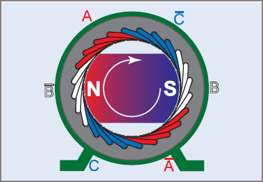
Figure 1 A three-phase machine
The phasor of the A-phase voltage VA is shown as the reference phasor, drawn horizontally to the right i.e. at 0º. The phasor of the B-phase voltage VB is drawn 120º after VA, which puts it at the bottom left of the diagram. Remember that the phasors rotate in a counterclockwise direction, so lagging phasors are clockwise from the reference phasor. The phasor of the C-phase voltage VC is drawn 240º after VA which puts it at the top left of the diagram, but note that it is also 120º counterclockwise from VA, which completes the cycle.
Generating a Three-Phase Supply
A three-phase supply is produced by an electric machine that contains three windings. The windings are separated by 120º (electrical), as shown in Figure 1, to naturally produce three voltage waveforms 120º apart.
The three phases follow in a fixed sequence, which is known as the ‘phase sequence’ or ‘phase rotation’. Therefore, the three phases must be identified to allow the sequence to be stated and to enable loads to be balanced across the phases. In some applications, the letters A, B and C are used as A-phase, B-phase and C-phase.
For general-purpose supply and distribution identification in Australia, the phases are given the color coding red, white and blue (prior to 1981 the colors were red, yellow and blue).
Phases may also be marked as L1, L2 and L3 meaning Line 1, Line 2 and Line 3. European standards often use U–V–W or u–v–w to represent the three phases.
As the phasors rotate, they pass through the reference position in the order red, white, blue. This sequence must be followed in connecting equipment on three-phase circuits, to ensure that motors rotate in the expected direction.
When three-phase phasors are drawn, the usual practice is to draw the red phasor (A) in the reference position; if there is a particular advantage, either the white (B) or the blue (C) phasor may be used as the reference as long as the sequence is still correct.
Advantages of a Three-Phase System
The advantages of a three-phase system include:
| 1. | For the same size or weight, a three-phase machine can produce higher outputs than a single-phase machine. |
| 2. | A three-phase machine can be smaller than a single-phase machine for the same power output. |
| 3. | The power delivered to or taken from a three-phase system has a more constant value. In a single-phase system, the power pulses at twice the line frequency. With three phases, the power pulses are six times the line frequency, with far less amplitude than single-phase power. Since the power is more constant, the torque of a rotating machine is more constant, and this results in much less vibration from the machine. |
| 4. | With one type of three-phase connection, there are two voltages available: 230/400 V. |
| 5. | In a distribution system, the total quantity of material needed for three conductors is less than that required for the equivalent single-phase system (due to higher efficiency). |
Three-Phase Winding Arrangements
Unlike DC machines, the poles in a 3Ø machine generally overlap and this is a factor in balancing the current and power of a 3Ø machine. Figure 2 shows a typical 24-slot stator lamination set. To use this for a 3Ø 4-pole electric motor, there must be three sets of coils for 4 poles fitted into 24 slots. This would normally result in a winding of 3 × 4 × 2 coils, meaning that two coils form one pole for one phase.
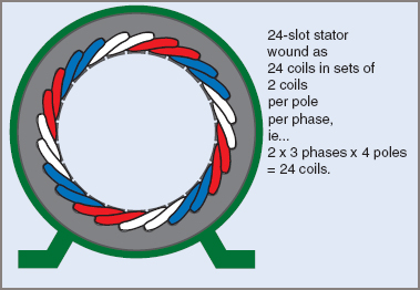
Figure 2 A three-phase induction motor winding
Phase A is drawn in red, with one side of the coils on the outside and the other on the inside of the laminated stator. Phase B is white and phase C is blue. The motor is ‘4-pole’, which means that there are four sets of coils (poles) for each phase. It can be seen that each phase occupies one-third of the total number of slots. A 4-pole machine has 720ºE in one complete rotation (360ºM).
Three-Phase Machine Alternator Construction
Basically an alternator consists of coils rotating in a magnetic field or, in an alternative form which has many advantages, the ac windings are stationary and the magnetic field system rotates.
The same basic principles apply equally to both single- and three-phase alternators, the only real difference being whether there is one winding or three identical windings.
