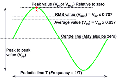
Here are some of the terms used to describe alternating waveforms:
| 1. | A ‘periodic function’ is an alternating wave that repeats itself in a cycle. |
| 2. | The number of times a wave repeats itself in one second is called the ‘frequency’ of that wave and is expressed in cycles per second or hertz. |
| 3. | The ‘period’ is the time taken for one cycle to complete itself and is equal to the reciprocal of the frequency (1/f seconds). |
| 4. | An instantaneous value of either a voltage or current waveform is a value expressed at only one instant of time. |
| 5. | Other values are often used to describe a sine wave or to perform calculations on values that are sinusoidal. |
Average Value of Sine Wave
An alternating sine wave is continually varying in value, so a meaningful standard must apply when describing its value, whether as a voltage or a current. Mathematically, the average value of a sinusoidal function is 2/π or 0.637.
Therefore the average voltage or current can be found from:
\[\begin{align}& {{V}_{av}}=0.637\times {{V}_{\max }} \\& {{I}_{av}}=0.637\times {{I}_{\max }} \\\end{align}\]
Note: these expressions are accurate only for sine waves.
The average value applies only for individual half-cycles and, since the direction of flow alternates, the average value of the second half-cycle is −0.637 and therefore the average flow for a complete cycle is zero. Average values are more applicable in circuits involving the conversion of ac to DC than in the usual ac circuits.
Average values are not suitable as a general basis for comparing alternating waveforms with direct current in terms of energy use or power. So it is essential that there is another value for comparing the real effects of alternating waves.
Root–Mean–Square Value of Sine Wave
The value of a sine wave that produces the same heating effect as DC can be obtained mathematically by a process called the root–mean–square (RMS) value of that wave. The term refers to the method by which it is calculated, which requires an understanding of calculus. Fortunately there is another method to explain why the calculus can be trusted.
If maximum values of voltage and current are used, the power can be shown by experiment or maths to be exactly one half of the power produced by the same DC values. That is,
\[Power\left( actual \right)={}^{Power\left( peak \right)}/{}_{2}={}^{{{V}_{\max }}{{\operatorname{I}}_{\text{max}}}}/{}_{2}\]
As the current is proportional to the applied voltage, the RMS factor must be applied to both the voltage and current maximum values. That is,
\[Power=\left( {}^{{{V}_{\max }}}/{}_{\sqrt{2}} \right)\times \left( {}^{{{I}_{\max }}}/{}_{\sqrt{2}} \right)\]
This results in a value of: 0.707Vmax × 0.707Imax or what we normally write as P = VrmsIrms.
The RMS value is often referred to as the effective voltage that will create an effective current flow to perform the same work as a DC voltage:
\[\begin{align}& {{V}_{rms}}=0.707\times {{V}_{\max }} \\& {{I}_{rms}}=0.707\times {{I}_{\max }} \\\end{align}\]
Note: these expressions are accurate only for sine waves.
Unless specifically stated otherwise, any given ac value should always be considered as the RMS value. The normal domestic ac supply is referred to as 230 V but the maximum value is 325 V.
Note: throughout this book, when working with ac, unless otherwise mentioned it is the RMS value that is intended.
The maximum value of a 230 V RMS supply can be found from the expression:
\[\begin{align}& {{V}_{RMS}}=0.707{{V}_{\max }} \\& {{V}_{\max }}={}^{{{V}_{RMS}}}/{}_{0.707} \\& ={}^{230}/{}_{0.707}=325.3V \\\end{align}\]
Crest Factor for Sine Wave
The ‘crest factor’ is used for waveforms in general and is simply a ratio that shows the relationship between the maximum value and the RMS value for a particular waveform:
\[\text{Crest Factor}={}^{{{V}_{\max }}}/{}_{{{V}_{RMS}}}\]
For example, for a sine wave:
\[\text{Crest Factor}={}^{{{V}_{\max }}}/{}_{0.707\times {{V}_{\max }}}=1.414\]
Since the crest factor is only a ratio, there are no units.
The crest factor is useful for indicating the maximum EMF that can be expected in ac waveforms of a known RMS value, thus indicating the value of the voltage that the insulation must withstand.
Form Factor for Sine Wave
For any waveform, the form factor is defined as the following ratio:
\[\text{Form Factor}={}^{\text{RMS Value}}/{}_{\text{Average Value}}\]
This is useful for indicating the general shape of ac waveforms. For example, for a sine wave:
\[FormFactor={}^{0.707{{V}_{\max }}}/{}_{0.637{{V}_{\max }}}=1.11\]
For waveforms in general, if the form factor is greater than 1.11, the waveform is more ‘peaky’ than a sine wave. On the other hand, if the form factor is less than 1.11, the waveform is more flat-topped than a sine wave. For example, the form factor of a square wave is 1.0.
Peak-To-Peak Value for Sine Wave
There will be occasions when the value of a wave from its positive peak to its negative peak is important. With most alternating waveforms, this is equal to twice the maximum value in either direction. For example, with a 230 V ac supply, the maximum value of voltage is found by dividing 230 by 0.707.
The same value can be obtained by multiplying230 by 1.414 (the reciprocal of 0.707 is 1.414 which equals √2). Either method gives 325.3 V as the peak value. Then the peak-to-peak value is twice this, or 650.6 V. This is useful when measuring the values of alternating waveforms on a cathode ray oscilloscope, as there is no zero voltage line on the trace.

