The main difference between primary batteries and secondary batteries is the ease with which secondary batteries can be recharged.
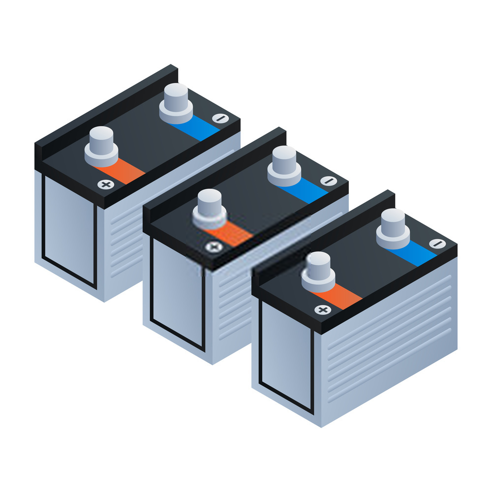
Lead–Acid Batteries
When compared with other types of battery of comparable size and weight, lead–acid batteries can deliver higher current for short bursts.
Variations in plate construction allow for individual specialized uses. For example, in automobiles, where the primary function is to start an engine, the plates are made thinner so that more of them can be fitted into the same-sized battery case. This increases the plate surface area for high-surge current for starting engines, although at the cost of thinner and therefore weaker plates, which in turn leads to a reduced battery life.
Battery Construction
In the fully charged condition, the active material of the positive plate is lead peroxide and the negative plate is spongy lead. The active materials have no rigid mechanical form or strength and it is necessary to mount them in a frame or grid. These are known as ‘pasted plates’ and are the most common form of construction (see Figure 1a). The grid usually has antimony added to the lead for rigidity and extra mechanical strength.
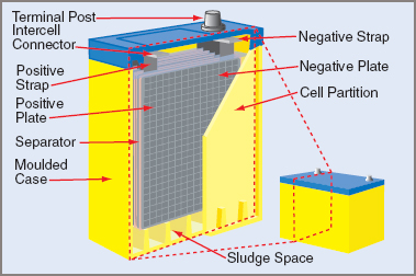
Figure 1a Battery Construction
Discharge Cycle
Sulphuric acid ionizes in the water to form positive hydrogen ions (2H+) and negative sulphate ions (SO4––). Lead atoms leave both plates and combine with the sulphate ions to form lead sulphate. At the same time, ionized oxygen atoms from the lead peroxide combine with the hydrogen ions to form water in the electrolyte.
For each lead atom that leaves the negative plate, an excess of two electrons is created on that plate, while for each oxygen atom that leaves the positive plate, a deficiency of two electrons is created. As the battery is discharged, the electrolyte is diluted with water. Under normal conditions of operation, the hydrogen and oxygen combine and no polarization occurs.
A discharged lead–acid battery must not be left standing too long without recharging, since the lead sulphate might fall away from the plates. If this occurs, the battery can never be completely recharged to its original state.
Furthermore, the sulphate might build up on the bottom of the battery and bridge the plates, so destroying the battery. Excessive amounts of sulphate might be formed if the battery is discharged below about 1.7 V/battery.
Charge Cycle
The battery can be recharged by connecting it to a source of electrical energy whose voltage is slightly greater than that of the battery. During recharge, the chemical reaction is simply reversed and the energy of the battery is restored.
Once the battery is fully charged, the hydrogen and oxygen still being liberated by the electrolysis of the water in the electrolyte cannot combine within the battery and instead vent to the atmosphere as gas.
Excessive gassing can lead to acidic vapors and the ejection of acid with the wet gas. Acid can then be deposited on surfaces adjacent to the battery, leading to a potential corrosion problem. In addition, overcharging can lead to the generation of heat within the battery, resulting in distortion of the plates.
One result of the internal resistance of the battery is a loss of voltage during the cycling of the batteries. On discharge the battery voltage is lower, while on charge the battery voltage has to be higher to overcome the losses within the battery.
Testing lead–acid batteries for state of charge (SoC)
The state of charge of a battery is often obtained by testing the density of the electrolyte. This is an indication only, since an exact value depends on such factors as the temperature of the electrolyte, the age of the battery and the previous history of the battery, including whether the battery has been overcharged or discharged, or subjected to excessive charging rates.
An instrument called a ‘hydrometer’ is used to test the electrolyte (see Figure 1b). Electrolyte is sucked up into the glass body of the hydrometer, where a float with a calibrated scale is read against the electrolyte level.
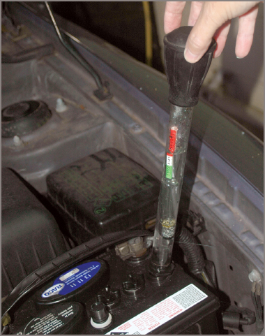
Figure 1b SG test of an automobile battery
The scale indicates the density of the electrolyte as mass per volume. As pure water has a density of 1 kg/l, or in SI terms 1000 kg/m3, the hydrometer measures the mass of the acid solution compared to that of water.
If the acid is mixed as usual, then a density of 1250 would indicate 1.25 kg/l or 1250 kg/m3. As the battery discharges, the SG of the electrolyte approaches 1 kg/l (that of pure water). So 1200 is a lower SG and therefore indicates that the battery has less charge than one with an SG of 1250. An SG of 1180 suggests that a battery is essentially discharged.
Sealed Lead–Acid (SLA) Batteries
A development of the secondary battery coming into prominence is the sealed secondary battery. Sometimes called ‘low-maintenance’ or ‘no-maintenance’ batteries, they are a variation of the basic battery. Sealed to prevent loss of electrolyte, they have a pressure valve fitted to allow them to vent to the atmosphere if the gases generated build up to predetermined pressures.
To allow the battery to operate in any position, it is necessary to ensure that the electrolyte maintains the electrical circuit between the plates. For successful operation, the battery must never be charged at a rate that will cause any gas to build up excessive pressure within the battery.
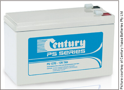
Figure 2 Sealed Lead Acid Battery
Initially the charging rate can be adequate but, as the battery approaches the fully charged condition, the charge rate must be reduced to a nominal one. This condition can usually be met by using constant voltage chargers, set at a maximum voltage in the vicinity of 2.26 V for sealed lead–acid (SLA) batteries. By preventing the loss of electrolyte, maintenance problems are reduced to keeping the battery terminals clean and ensuring that the voltage regulation is correct.
Gel Batteries or Sealed Lead–Acid Batteries
Small sealed batteries using the lead–acid principle are available in either rectangular or cylindrical shapes for portable applications. The rectangular package uses the conventional flat-plate design, while the cylindrical one uses plates rolled around each other.
In both types, the electrolyte is dilute sulphuric acid which has been treated to make it jelly-like. It is then called a ‘gel’ and a limited amount is provided to ensure that gassing is kept to a minimum.
Various methods are used for the insertion of the gel, the intention being to ensure that there are no air bubbles left in the gel when it is in place. As the gel dries, small cracks appear and form a repository for any gases generated in the battery during charge and discharge cycles.
These batteries are resistant to leakage and can be used in any position because of their unspillable electrolyte. They are sealed to prevent the entry of oxygen and dust from the atmosphere and consequently contamination is practically non-existent. Except for cleaning and charging, batteries of this type are almost maintenance-free.
The various models range in capacity from 1 to 10 ampere-hours. The battery has a larger area of negative electrode than positive electrode, to ensure that the positive electrode is charged before the negative electrode. Oxygen, which is the first gas generated, moves through the gel and combines with the negative plate, so limiting further negative plate charge and restricting the formation of hydrogen.
As the decomposition of water and the generation of gas are minimized, the electrolyte needs no topping up while in service. The containers are, however, provided with a vent that opens when pressure builds to high values. The battery then reseals itself.
Performance characteristics of gel batteries are similar to those of conventional lead–acid batteries. There is an absence of the ‘memory effect’, a long standby life and a lower cost than other sealed secondary batteries.
As with other types of lead–acid battery, gel batteries can provide high discharge currents for limited periods. They have been found to have a long shelf life in the charged condition and consequently have found many uses as a power source where they can be left untended for periods of time. Such uses include in power boats and cameras, where they are simply left sometimes for weeks at a time, but are able to supply an appreciable current when required.
There are precautions that have to be taken when charging and discharging:
Charging
Constant-voltage charging appears to produce the best results with a voltage that does not exceed approximately 2.45 V per battery. This equates to 14.7 V for a 12 V battery and is considered the fast charging rate.
With constant-voltage charging, the current gradually decreases and, when it has reached a current of approximately one-hundredth of the initial charging current, the battery is considered fully charged.
With a floating charge for batteries that are on standby use, the recommended charge is 2.25 V per battery. This equates to a battery voltage of 13.5 V for a 12 V battery. The aim is to limit the rate of the gas being produced in each battery during charging, so that it has time to be absorbed into the gel and does not cause excessive pressures within the case.
Discharging
For the 20-hour rate, the discharge current should be one-tenth of the ampere-hour rating of the battery. It will of course deliver much higher currents for short periods. It is quite common for this higher current rate to be ten times the ampere-hour rating of the battery. This in turn discharges the battery in a much shorter time. It is better for a gel battery to be kept at full charge and not allowed to discharge to a very low state of charge.
Applications
Electronic devices, security, pleasure boats and yachts, motorcycles, cameras, portable stereo equipment, amateur radio transmitters and golf buggies.
Nickel–Iron (NiFe) Batteries
There are two major types of nickel–alkaline batteries. One has nickel–iron electrodes and the other has nickel–cadmium electrodes. Each type has a similar basic construction and an operating voltage of 1.2 V.
Both positive and negative electrodes are usually made of a powdered material held in pockets manufactured within a pressed steel frame. The active positive material is nickel hydroxide. The negative plate material is powdered iron. The battery case is often a steel pressing but for some purposes may be made of plastic.
The electrolyte is mainly potassium hydroxide (caustic soda) dissolved in water, but may have some additives to lower the internal resistance of the battery.
The battery itself often contains several plates of each polarity, as in the lead–acid battery. The separation between plates is often achieved by round pins instead of flat separators. When a steel battery container is used, it must be insulated from the plates as well as from other batteries.
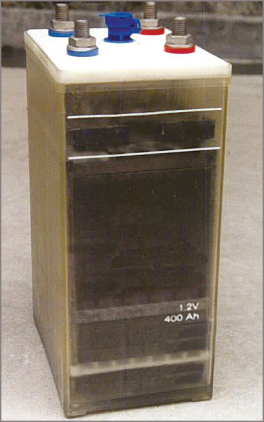
Figure 3 NiFe battery NB 1.2 V at 400 Ah
Discharge Cycle
On the discharge cycle, the electrolyte solution releases potassium ions (K+) and hydroxide ions (OH–). The potassium ions attract hydroxide ions from the positive plate, effectively converting the nickel hydroxide into another form of hydroxide, Ni (OH) 2, and leaving a net positive charge.
Hydroxide ions from the electrolyte attach themselves to the negative plate material, creating iron hydroxide, Fe (OH) 2, and leaving a net negative charge. While the battery is discharging, the electrolyte appears to break down into ions and then recombine. The overall result is that the electrolyte condition remains virtually unchanged, unlike that of the lead–acid battery.
Charge Cycle
On the charge cycle, the electrolyte breaks down into potassium ions (K+) and hydroxide ions (OH–) as before, but the migration of hydroxide ions is in the reverse direction. Potassium ions attract hydroxide ions from the negative plate, converting it back into iron. These ions then combine to form electrolyte and other hydroxide ions move across to the positive plate, there converting the nickel-hydroxide plate material back into its original form, Ni(OH)4.
Again the electrolyte takes no real part in the process, merely being the vehicle for the passage of hydroxide ions from one electrode to the other.
A battery may be charged at any rate that does not produce excessive gassing or temperature rise. A battery voltage which does not exceed 1.7 V will generally meet these conditions, on the assumption that the charge is terminated when complete.
Correct charging is an important factor in the maintenance of a nickel–iron battery and an effort should be made to ensure that the correct amount of charge, at the proper rate for the particular battery, is given.
Testing Nickel–Alkaline Batteries
The specific gravity of the electrolyte of a nickel–alkaline battery should be a value within the range 1.120–1.250. Over a period of time this can decrease (at a rate dependent on how the battery is treated). Under normal conditions, the electrolyte plays no active part in the battery’s cycle and cannot give an indication of the state of charge of the battery.
Accordingly, a hydrometer cannot be used successfully as a test instrument. If a battery is fully charged, it is subject to gassing; if the charge rate is too high, then a battery is also subject to gassing whether fully charged or not, so this is no indication of the state of charge.
The only practical method available is the high-discharge test. As a general guide, the open-circuit voltage should be approximately 1.2 V. A battery that needs attention would give a voltage in the vicinity of 1.1 V.
Note that the battery is subject to the same internal resistance efficiency as the lead–acid battery, although the internal resistance values are somewhat higher for the nickel–iron battery.
The charge curve also shows that the charging voltage tends to rise rather steeply as the battery approaches full charge. The charging voltage for a 6 V battery assembly will rise abruptly to 10 V and beyond when approaching the fully charged state at high rates of charge. Steps then have to be taken to prevent further charging taking place and before battery damage occurs.
Nickel–Cadmium (NiCd) Batteries (Vented)
Somewhat similar to the nickel–iron battery, the electrodes consist of compounds of nickel and cadmium with an electrolyte of potassium hydroxide. The voltage per battery is 1.25 V. During discharge, trivalent nickel hydroxide is converted to the divalent state, the reverse occurring during charge. The negative plate in the charged state is metallic cadmium, which is converted to cadmium hydroxide during discharge.
Nickel–Cadmium (NiCd) Batteries (Sealed)
Along with other types of sealed batteries, nickel–cadmium batteries have the following special construction features to prevent a build-up of pressure caused by the generation of gases during the charge cycle:
| 1. | negative electrodes of larger capacity than the positive electrodes |
| 2. | plate separators made particularly permeable to oxygen |
| 3. | a limited amount of electrolyte. |
The construction method ensures that the positive plate reaches a state of full charge before the negative plate. The oxygen given off can pass through the plate separator and is absorbed by the negative plate. The limited amount of electrolyte available to the electrodes appears to assist in this transfer of oxygen. The electrolyte itself has a jelly-like consistency and is held in position between the electrodes by the battery construction.
The electrolyte does not have to be replaced during the life of the battery and other maintenance is minimal, the only necessary procedure being to keep the batteries relatively clean and charged. They can operate in any position, have a rugged construction and long storage life and perform comparatively well over a range of temperatures.
The sealed battery has a higher energy density per unit volume, but the open type has a higher energy density per unit weight.
Sealed batteries operate best at temperatures of between 20ºC and 30ºC but can function outside this range. A higher operating temperature causes increased separator deterioration and shortens battery life. Lower temperatures cause a temporary reduction in capacity. The open-type battery is not affected to such a degree and can operate more effectively through a wider range of temperatures.
Memory Effect
A feature of the nickel–cadmium battery is the effect on battery capacity caused by previous charge and discharge cycles. Often called the ‘memory effect’, it means that battery capacity can be reduced by incomplete or shallow charge and discharge cycles. The situation can be rectified by cycling the battery through several deep discharges, followed by full slow-rate charges.
Multi-battery batteries should not be discharged to such a low voltage that the lowest capacity battery can be driven into a reversal of polarities.
The charging of sealed nickel–cadmium batteries is usually by the constant-current method at a rate recommended by the manufacturer. This is often over a 10- to 16-hour rate, to prevent gases being generated in the battery at a rate beyond the absorption capacity of the battery. If this rate is exceeded, internal pressures within the battery can rise to excessive levels, causing the battery to vent to the atmosphere or in extreme cases to burst open.
Fast-charging methods are occasionally adopted, but the charging units must have built-in protection methods. Charging at the 16-hour rate means that a 1 Ah battery is charged at 1/16th of an amp for 16 hours.
The major features the charger needs to monitor are output voltage and battery temperature. On high charging rates, the output voltage rises sharply when the state of maximum charge is reached. Charging must be stopped abruptly at this point.
Below 0ºC, charging rates must be decreased, as the recombination of oxygen becomes slower and high pressures must be avoided within the battery.
Nickel–Metal Hydride Batteries (NiMH Batteries)
Nickel–Metal Hydride battery is a recent development, being a secondary type battery. It is fully rechargeable and is capable of many charge/recharge cycles.
It is claimed that this battery can go through several hundred of these cycles if not abused in any way and can last for many years. For its physical size and mass, it has a high energy capacity (i.e. it has a high energy density) and will withstand comparatively high rates of charge and discharge. In some applications this can be a decided advantage.
Like the lithium battery, it maintains its output voltage well into its discharge cycle, even at the higher rates of discharge.
Its shelf life is somewhat limited because of its loss of charge of around three per cent per day, but it does not appear to suffer from any memory effects that affect some other battery types.
The negative electrode or cathode consists of a hydrogen-absorbing alloy, the actual material being restricted information. The positive electrode or anode is nickel oxide, with the electrolyte of potassium hydroxide. The whole assembly is placed into a sealed metal can with provision for a relief valve to prevent high internal pressures.
The overall charge/discharge equation approximates:
$\begin{matrix}Ni{{\left( OH \right)}_{2}} & + & \begin{matrix}M & \leftrightarrow & \begin{matrix}NiO\left( OH \right) & \begin{matrix}+ & H \\\end{matrix} \\\end{matrix} \\\end{matrix} \\\end{matrix}$
Where M = hydrogen-absorbing metal alloy
Applications include long-term supplies of limited amounts of use, mobile phones, cordless phones and general portable electronic devices.
Silver Oxide–Cadmium Batteries
In terms of secondary batteries, these are a comparatively recent development. They have a higher energy output per unit mass than either lead–acid or nickel–cadmium batteries.
In the charged condition, the positive plate consists of silver oxide and the negative plate of cadmium, the plates being separated by a semipermeable membrane, with potassium hydroxide as the electrolyte.
As with nickel–cadmium batteries, there are two types: vented and sealed. The nominal voltage is approximately 1.3 V per battery, but this drops fairly quickly to about 1.1 V per battery and this is maintained for a considerable proportion of the discharge cycle.
Lithium–Iron Batteries
Lithium-based batteries have been the main recent area of research and, although some of the technologies were discovered over 10 years ago, they are still in the early development stages, especially considering that the lead–acid battery has a 140-year head-start on them.
Some lithium technologies were known for thermal runaway, including some that exploded in laptop computers. The more promising technology at present seems to be lithium–iron–phosphate (LiFePo), which has apparently overcome the thermal runaway issue, uses non-toxic materials and its materials are in relatively good supply, including iron.
LiFePo batteries have a greater specific energy density than most current technologies, high nominal voltage (3.6–3.7 volts), high discharge rates and low DOD. LiFePo batteries are often made cylindrical as shown in Figure 4. A typical car battery requires only four of these batteries in series to make 12 volts (14.4 V), is half the size and weight of a lead–acid equivalent and has a greater cranking current.
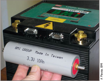
Figure 4 Lithium Ion Phosphate Battery
Battery size for 15 Ah at 3.7 V is 40 mm diameter and 150 mm long. Although initially expensive, the price will no doubt come down as production techniques are polished and R&D costs are covered. LiFePo or similar technology batteries are expected to become more common over the next few years.
