Figure 1 illustrates a simple DC circuit consisting of a resistor with which an inductor is added in series. We are interested to see what the effect of this inductor to the circuit is.
The effect of an inductor in an electric circuit is always to oppose a change in the circuit current. For instance, at the instant the switch is closed, current tends to increase from zero to a value that depends on the voltage and resistance in the circuit.
An inductor wants to keep the current unchanged. Eventually, after a short period of change, the current settles at a value and remains constant for this DC circuit.
- Adding an inductor in an electric circuit is analogous to adding a flexible (stretchable) tank (reservoir) to a hydraulic pipeline. When the tank stretches, its volume changes.
- When the valve in the pipeline is opened to let water flow, the flowing water must fill the flexible reservoir before it can continue its normal flow. Thus, part of the flow is used to fill the reservoir.
- Once the reservoir is filled, water flow continues in the pipeline at its normal rate. In other words, the flow of water is initially resisted and limited for a short period of time but afterward will have a continuous and constant current.
- The effect of an inductor in an electric circuit is to oppose a change in the circuit current (keeping the current unchanged).
- Here again, it is interesting to know how long it takes for the electric current in Figure 1b to reach its constant value or for the water in Figure 2b to reach its normal flow.
Associated with the circuit resistance R and inductance L values, we may define a time constant (similar to the case for a capacitor) as follows:
\[\begin{matrix} \tau =\frac{L}{R} & {} & \left( 1 \right) \\\end{matrix}\]
When L is defined in henries and R in ohms, τ will be in seconds. This equation implies that for smaller values of R the duration of the effect of the inductor is longer. It takes approximately 5× the time constant for the current to reach its constant value.
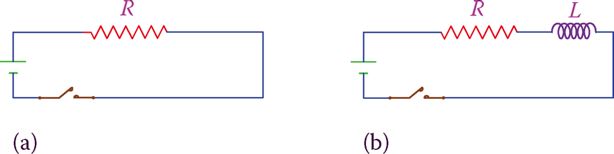
Figure 1: Adding an inductor in series with a resistor in a DC circuit. (a) Original circuit. (b) Circuit with an inductor.
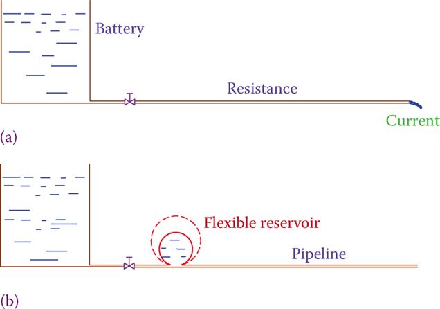
Figure 2: Analogy of a hydraulic system to an electric circuit when an inductor is added. (a) A circuit without an inductor. (b) Circuit with an inductor.
RL Circuit Time Constant Calculation Example
What is the time constant in a circuit containing a resistor and a coil in series? The resistor has a value of 51 Ω, and the coil has an inductance of 11 mH and a resistance of 4 Ω.
Solution
Substituting in Equation 1 gives
\[\tau =\frac{L}{R}=\frac{0.011}{51+4}=0.0002\sec \]
It takes approximately 5× the time constant for the effect of an inductor in a DC electric circuit to disappear.
RL Circuit Time Constant
In the same way that a capacitor causes a delay for the voltage change in a circuit, because of its intrinsic electricity storage property, an inductor in a circuit causes a delay. However, the delay caused by an inductor is because of the property of an inductor to resists a change in the current in the circuit it is a part.
The time constant for a circuit containing an inductor and a resistor is defined by
\[\tau =\frac{L}{R}\]
When L is henries and R is in ohms the calculated value of the time constant is in seconds.
All that was said about the time delay for changing voltage in a circuit containing capacitors and resistors and the corresponding graphs is true for a circuit having an inductor in it. However, in this case, the values and the percentage of change shown at the end of periods T, 2T, 3T, etc., corresponds to changes of current in a circuit and not voltage.
