Electrical Schematic diagrams convey specific information to the technician. They illustrate such items as the size, type, component part number, and component location in relationship to the other circuit components.
Diagrams can be used for installation, fabrication, troubleshooting, or to explain the circuit’s operation or purpose. Symbols are used to represent circuit components. Wires or conductors are usually shown as lines. Their connections can be shown a number of ways. See Figure 1.
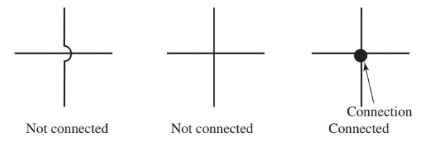
Figure 1. Schematics of wires. Two wires can cross on a schematic diagram and not be electrically connected. A dot must be shown at the intersection for a connection to be made.
Schematic Diagram
One primary type of electrical drawing you will encounter is the schematic diagram. See Figure 2. This is a typical schematic diagram. It shows what parts are needed and how they connect to one another. The distance between the components does not represent the actual distances.
The main purpose of the schematic diagram is to show how the components relate to each other. The diagrams show which components are in series or parallel with each other. Schematics are an extremely valuable troubleshooting tool.
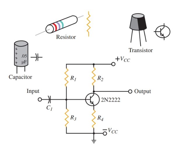
Figure 2. A typical schematic diagram illustrates the location of the components and how they relate to one another
The combination of meters, wiring diagrams, schematics, and electronic theory allow a technician to find circuit problems. Many circuits are impossible to troubleshoot without the aid of schematics and the application of electronic theory.
Elementary Line Diagram & Wiring Diagram
Figure 3 is a comparison of an elementary line diagram and a wiring diagram. This illustration shows the operation of a typical stop-start motor control system.
The elementary line diagram on the left is similar to a schematic diagram. It is used primarily in industrial processes to illustrate how a system’s electrical controls relate to each other.
On the right is the actual wiring diagram. This would be used to connect the control system.
The elementary diagram clearly illustrates how the circuit operates, while the wiring diagram illustrates the relative positions of the connection points and components as they would actually be found in the equipment. Each diagram has its own purpose.
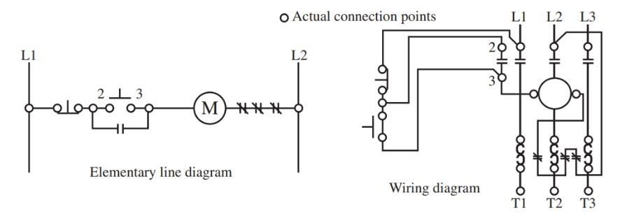
Figure 3. Both the elementary line diagram and the wiring diagram shown here are of the same electrical system,
The elementary line diagram is used to clearly express how the circuit works. The wiring diagram is used to install the system.
Sometimes a block diagram is used to show how an overall system works. Look at Figure 4 to see a block diagram of a typical am radio. The components, such as the amplifier, are grouped together in stages.
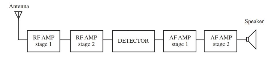
Figure 4. A block diagram is used to illustrate how major electrical systems relate to each other.
Figure 5 is a typical plan of the electrical circuits to be installed in one room of a residence. The drawing indicates the general location of switches, outlets, and lighting.
Descriptions of wire sizes, switch amperages, and breaker sizes are not shown on this type of plan because the electrician is trained to be familiar with electrical codes dealing with these factors.
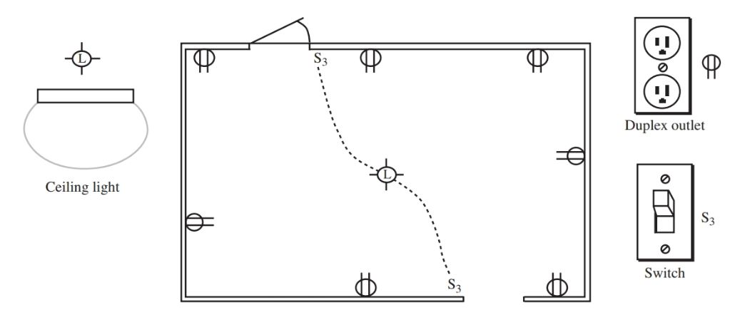
Figure 5. Typical layout of a residential room to be wired by an electrician.
When constructing an electrical system, you may find using a circuit design software program beneficial. Circuit designers rely heavily on computers and software for modern electronic circuit design. See Figure 6.
In these software programs, components can be selected from menus and placed on the drawing area. Electronic characteristics for each component, such as resistance values, current ratings, and voltage limits, can also be added.
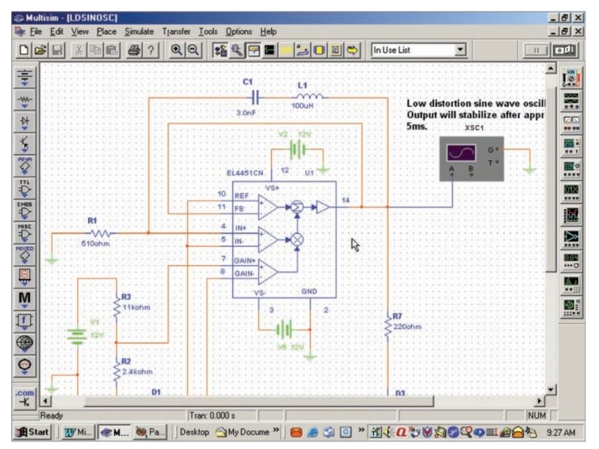
Figure 6. Screen capture of Multisim Electronics Workbench.
Software systems not only can be used to draw out electronic circuitry, but they can also actually be used to simulate the circuit as though it was constructed with electronic components.
Virtual meters can be connected to different points in the circuit for experimentation and testing. A complete list of materials can be generated from the circuit design.
The pattern required for a printed circuit board can be printed. This makes the design and testing process quicker and easier than if the circuit was built using actual components. Once the circuit design is tested for satisfaction, the circuit can be built using actual components.
