There are several common circuit devices that are present in most electrical and electronic circuits. They provide a means of controlling electron flow through the conductor paths and provide for safe operation of circuits. The three important items discussed here are switches, connectors, and circuit protection devices.
Switches
Switches are installed in circuits to control the flow of electrons through the circuit. They can be categorized by their actuator and electrical switching path. The actuator is the mechanical device that causes the circuit to open and close.
Various types of switches are illustrated in Figure 1. The schematic symbol associated with each type of switch is also included.
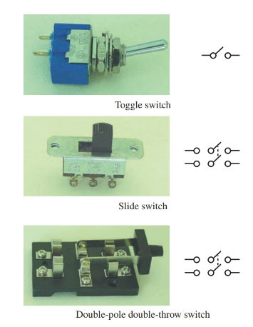
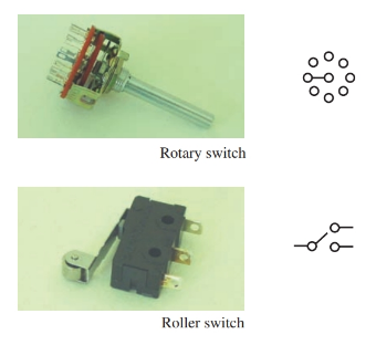
Figure 1. Typical switch types. Notice how many have the same electrical symbol but different actuators.
Some of the most common actuators are the slide, toggle, rotary, and push button. As you can see, the name of the switch indicates the type of actuator used to turn the circuit on and off.
The electrical circuit inside the switch is described in terms of poles and throws. The simplest type of switch is the single-pole single-throw switch, which is abbreviated SPST. The term single-pole means that the switch provides one path for the electron flow and that it can be turned on or off. The term single-throw means that the switch controls only one circuit.
A single-pole double-throw switch (SPDT) has one common connection point and can complete a circuit path to two different circuits. However, only one circuit can be completed at a time. There are many possibilities and combinations for a switch of this type.
A useful application of the single-pole double-throw switch is its ability to control a load, such as a lamp, from two different locations. In residential wiring systems, the single-pole double-throw switch is referred to as a three-way switch.
In Figure 2, two single-pole double-throw switches are connected to a lamp. Either switch is capable of turning the lamp on or off.
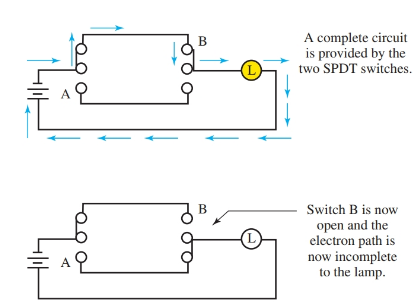
Figure 2. Two single-pole double-throw switches (SPDT) can be used to control a lamp from two different locations.
A double-pole double-throw switch (DPDT) has two common connection points and can provide two circuit paths simultaneously. The DPDT switch is like having two SPST switches connected in parallel.
Switch Ratings
Switches are rated for ampacity and voltage.
The ampacity rating of a switch is an indication of how much current it can safely handle.
The voltage rating is the maximum voltage for which a switch is designed.
Exceeding the maximum voltage rating will cause the electrical-mechanical circuitry inside the switch to fail. For example, if a toggle switch is rated as one amp and 24 volts, a current in excess of one amp will burn out the switching circuitry inside the switch. If the 24-volt switch circuit sufficiently to stop the flow of electrons. This action will result in a dangerous situation that can melt the switch’s insulation and short circuit the switch.
Connectors
There are many types of connectors used with electrical conductors. The type of connection used varies according to the type and size of the conductor, the purpose served by the connection, and the type of device to be connected.
Look at Figure 3. You will see many common types of connectors. One general classification is solder less connectors. A solder less connector does not require the use of solder to make the connection. These connectors generally require a crimping tool. The crimping tool squeezes the connector to the conductor. Figure 3 shows common wire crimps on terminals and splices.
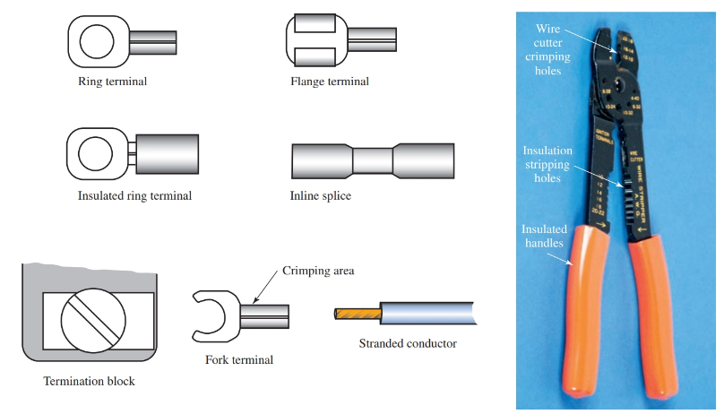
Figure 3. Some wire connectors are made to be crimped on the end of stranded conductors. After the connector is crimped on the wire, the wire can be easily secured under a termination block screw.
Some types of connectors use screws and bolts to form the mechanical connection to conductors. These connectors are used primarily for larger conductors. See Figure 4.
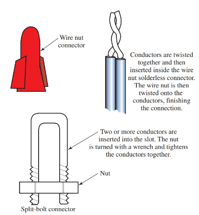
Figure 4. Two types of solder less connectors are the wire nut connector and the split-bolt connector. The wire nut is used extensively in residential and commercial wiring. The split-bolt connector is used mainly on large diameter conductors.
Circuit Protection Devices
Common circuit protection devices are fuses and circuit breakers.
Fuse
Fuses, such as those shown in Figure 5, are constructed from small, fine wire. This wire is engineered to burn if certain amperages are exceeded. Fuses are sized by their voltage and current capacity, primarily current.
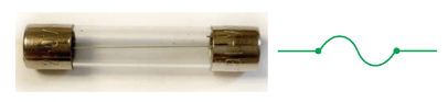
Figure 5. A typical fuse and the schematic symbol that represents the fuse.
For example, a three-amp fuse is designed to burn and open the circuit when the current exceeds three amps. A load that draws three amps or greater will generate sufficient heat in the fuse to melt the fuse link inside the glass tube. The time required to melt the fuse link is inversely proportional to the amount of overload. This means that the higher the overload current, the faster the melting action occurs. When a fuse melts, it must be replaced.
Circuit breaker
A circuit breaker, sometimes called a reset, is another device used to protect a circuit from overload and short circuit conditions. See Figure 6.
The main advantage of a circuit breaker over the fuse link is that the circuit breaker need not be replaced after tripping. It can be reset by moving the handle to the off position and then returning it to the on position.
Some circuit breakers have an actuator similar to a push button switch. These breakers are pushed in to reset after tripping. Circuit breakers and resets require a waiting period to allow the internal trip mechanism to cool down.
Most homes today use circuit breakers as the safety device to prevent overloads. Overloads could result in house fires.
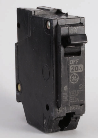
Figure 6. A typical circuit breaker.
Circuit breakers are produced with two different tripping methods.
One method uses bimetallic strips. A bimetallic strip is a metal strip made of two different types of metal. Different metals expand at different rates. Heat generated from the overload condition causes the bimetal trip to expand. The different metals expand at different rates. This causes the breaker’s trip mechanism to bend and break contact. Some trip mechanisms are adjustable to allow for a more precise trip current.
A second tripping mechanism uses magnetism to operate. The circuit current runs through a coil. As the current increases through the coil, the amount of magnet- ism in the coil increases. When a predetermined point is reached, the tripping mechanism operates and opens the circuit.
The magnetic circuit breaker is much faster and more accurate than the bimetallic circuit breaker. The magnetic circuit breaker, however, is more expensive than the bimetallic type.
