A basic multimeter can measure the three basic electric values (i.e., voltage, current, and resistance), but more functions can also be included in a multimeter. Initially, there are two types of multimeters, analog and digital.
A multimeter is a must-have tool for someone working with electricity and electronics. It is always necessary to verify values, to measure voltage, current, and resistance values in a circuit for diagnostic purposes, or to identify a damaged component.
Analog Multimeter
Analog multimeters work based on the deflection of a needle from its zero position point. During a measurement, one needs to read the correct value just under the needle.
The main part of an analog meter is a galvanometer that consists of a small winding. The winding can rotate about a pin, and a needle is attached to it. It also has a spring to return the needle to the home (zero) position. Depending on the intensity of the current through the winding, it deflects from its rest position. Thus, a galvanometer is a current-sensitive device.
By making some changes to a galvanometer and adding more components, it can be used as an ammeter, a voltmeter, an ohmmeter, and other measurement devices. The deflection of the needle in an analog meter is always from left to right.
Galvanometer: A device consisting of a needle attached to a coil that can rotate around a pin shaft as a result of an electric current flowing through the coil. The coil behaves also as a spring, limiting the motion of the needle. A galvanometer is used to measure electric current, but the needle position can be graduated for other electric entities, like voltage.
Ohmmeter: Device for measurement of electric resistance.
Figure 1 shows a typical analog multimeter. It has a selector rotary switch by which one selects the category and range of values to be measured.
Not all the meters are built the same way and have the same range of values and the same number of terminals. More details of the switches and terminals in the multimeter of Figure 1 are illustrated in Figure 2.
In addition to the main selector switch for changing from volt to ohm or amp and selecting their range of values (e.g., 100 mA, 500 mA, 25 V, and 500 V), there is another switch for AC, –DC, and +DC.
There are two main terminals for connecting the black (common) and red leads, but additional terminals are used for 10 A current (current larger than 500 mA and up to 10 A), 500 V and 1000 V (higher voltages).
For measuring these relatively high values the black lead still goes to the common terminal, but the red lead must be inserted into the appropriate hole.
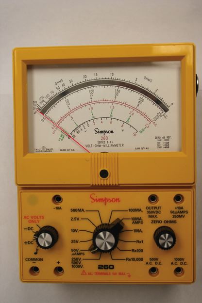
Figure 1 Typical analog multimeter.
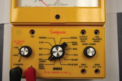
Figure 2 Switches and terminals on an analog multimeter.
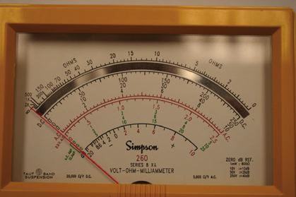
Figure 3 Various graduations on a typical analog multimeter.
Figure 3 illustrates the set of various readings for the multimeter shown in Figure 1. As can be understood, these graduations are different, and for one position of the needle, there are various numbers.
Each graduation corresponds to one or more selector switch positions. For instance, for a selector switch range of 2.5, 25, and 250 (see Figure 2) one must use the graduations ending in one of these numbers, whereas for other selections the numbers are between 0 and 10 (which must be multiplied by a power of 10, accordingly).
Also, in the meter shown, the AC values are shown in red, whereas the DC values are in black.
Note that the zero value for ohm measurement (top scale) is to the extreme right (all the other zero values are on the extreme left). This is because a higher resistance value leads to a lower current value (see Ohm’s law in this chapter) and vice versa.
Digital Multimeter
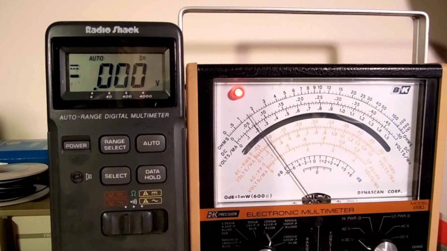
A typical digital multimeter (DMM) is depicted in Figure 4. It has a rubber casing that protects it against shocks and scratches. Normally, it is easier to work with a digital multimeter because it directly gives the measured values in numbers.
A DMM does not have any moving parts and works based on converting an analog reading to a digital value.
Digital multimeter (DMM): A device to measure resistance, current, voltage, and other electrical parameters, in which the reading is automatically adjusted and displayed by 3 or 4 digits, as compared to analog multimeters in which the position of a rotating needle represents a measured value.
Similar to an analog multimeter, a DMM has a common terminal to which the black lead is connected and the red lead goes into one of the other terminals, depending on the design of the DMM.
In the DMM shown in Figures 4 and 5 the red terminal is inserted in the hole to the right of the common (com) terminal, but for measuring current (based on its value if it is in the order of amps or much smaller) the other two holes are used.
It is always safer to use the higher current terminal first (the one on the left) before using the middle terminal for higher precision. In this way, you do not subject the fine meter to a current much larger than its capacity, which can damage the meter (or blow its fuse).
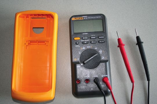
Figure 4 Typical digital multimeter (DMM).
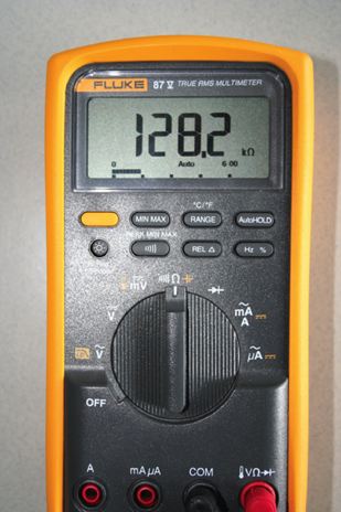
Figure 5 Selector switch and the display of a typical DMM.
In the multimeter of Figure 4 the switch can be positioned to off, when the meter is not in use, or it can be set for AC voltage, DC voltage, small DC voltage (mV), resistance (ohm, Ω), and current (Ampere A, milliamp mA, and μA micro-amp). There is one more selection for the diode (test).
Better DMMs have four digits, as shown in Figure 5. Some cheaper DMMs have only three digits. Normally, on the basis of the measured values, the scale is automatically adjusted; for instance, in Figure 5 the scale is automatically set to kΩ (appearing on the screen).
Measuring Resistance using Digital Multimeter
A resistor’s resistance or the resistance of the part of a circuit can be measured by an ohmmeter or a multimeter. An ohmmeter or the ohmmeter part of a multimeter works based on measuring the current in a circuit where the item to be measured constitutes the main load of that circuit.
Nevertheless, the graduations are made in terms of resistance values, not current values. In this sense, the following differences exist between an ohmmeter and a voltmeter or ammeter:
- An ohmmeter needs a battery to power its circuit, whereas for measuring current or voltage, no battery is needed because there is already a current (when the switch is closed).
- Because current is measured, using Ohm’s law, for a smaller resistance, there is a large current and for a larger resistance, the current is smaller. This necessitates that the zero reading for resistance (in an analog meter) be at the extreme right side of the scale (the highest current) and the larger resistance values are on the left side.
- Because the ohmmeter battery loses its strength with time, an ohmmeter has a zero adjustment knob that is used to bring the needle to zero reading. It is always necessary to adjust the zero reading before any measurement is made with an analog ohmmeter. This can be done by directly putting together the ends of the two leads, then turn the adjustment knob to bring the needle to zero.
- Measuring resistance must always be performed when the power to a circuit (the resistance of a part of which is to be measured) is turned off. Otherwise, the reading will be erroneous.
An ohmmeter can be used for measuring and verifying the value of any resistor or resistive element. In addition, it can be used for checking the continuity of a circuit to see if any part of a circuit is open or there is any short (two points unnecessarily contacting) in the circuit.
When measuring the resistance of the part of a circuit, the power to the circuit must be off.
Checking a Capacitor and an Inductor with an Ohmmeter
An ohmmeter (usually, only analog meters) can also be used to check if a capacitor is good or damaged. If a capacitor is damaged, it either becomes short (when the two plates of the capacitor contact each other) or open (contacts are lost).
To check a capacitor, it is connected to an ohmmeter. If it is short, then it shows a high current (near zero resistance) and the meter needle stays at the same point.
If it is open, then it shows a very high resistance (the needle stays in the very left side of the meter). If the capacitor is good, the needle of the meter quickly moves to the right and slowly goes back to the left.
In a similar way, we can use an ohmmeter to see if an inductor is fine or if it is damaged. A digital or an analog multimeter can be used.
Note that in a DMM when the value to be measured is beyond the range of values selected an overload sign will appear on the screen by the letters “OL” as shown in Figure 6.
Specifically, when measuring resistance, an open circuit (equivalent to a very high resistance measured) is realized if the meter shows OL.
An inductor can be shorted or can be open. If after connecting its two ends to an ohmmeter high resistance is noticed, then it is open. A short inductor shows zero resistance. A good inductor shows a small value of resistance but not zero.
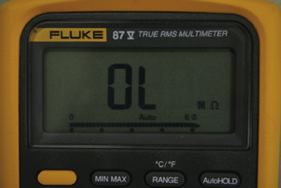
Figure 6 Very high-value resistance or an open circuit.
