The different types of dc motors share the common names of dc generators such as shunt, series, and com- pound. The construction of the motors is similar to the generator counter parts.
Shunt DC Motor
In the shunt motor, the field windings shunt across, or in parallel to, the armature, Figure 1. The shunt motor is commonly called a constant speed motor. It is used in driving machine tools and other machines that require relatively constant speed under variable loads.
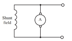
Figure 1. Schematic of a shunt motor.
In the shunt motor, both the field and the armature are connected across the power line. Under no-load conditions, the counter emf is almost equal to the line voltage. Very little armature current flows, and very little torque is developed.
When a load is applied and the armature decreases its speed, the counter emf also decreases. The decreased counter emf increases the armature current and the torque. When the torque matches the load, the motor remains at constant speed, Figure 2.
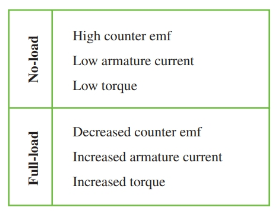
Figure 2. Shunt motor load conditions.
The total current used by this motor is the sum of the field and armature currents. The input power may be computed using Watt’s law:
Note, however, that the output power will be somewhat different because the motor is not one hundred percent efficient.
Series DC Motor
In the series wound motor, the field windings are connected in series with the armature windings, Figure 3. All the line current must flow through both the field and armature windings. Under loaded conditions, the counter emf opposes the line voltage and keeps the current at a safe level.
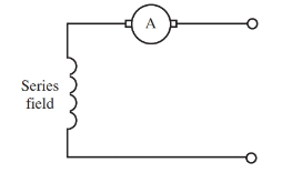
Figure 3. Schematic of a series motor.
Why should not we operate Series Motor without Load?
If the load were suddenly removed, the armature would speed up and develop a higher counter emf. This higher counter emf would reduce the current flowing through the field and reduce the field strength. In turn, the motor would increase its speed because:
\[\text{Speed=}\frac{\text{Counter-Emf}}{\text{Field Strength }\!\!\times\!\!\text{ K}}\]
This action builds upon itself and, eventually, the motor would reach a speed where the armature would fly apart because of centrifugal force. Thus, a series motor is never operated without a load.
Furthermore, the series motor should be connected directly to a machine or through gears. It is not safe to use a belt drive from a series motor to a machine. If the belt should break or slip off, the motor would “run wild” and likely destroy itself.
The National Electrical Code requires that a series motor have a control system that disconnects the power to the DC series motor if the mechanical load should become disconnected from the motor. One such system wires a current relay directly in series with the dc motor armature circuit. There must be a sufficient current passing through the relay coil for the coil contact to remain closed. When the series motor becomes disconnected from its mechanical load, the motor speeds up. As the motor speeds up, the counter emf increases and the current through the armature and relay are reduced. The counter emf continues to cause the current value to drop until the relay drops open, disconnecting the armature circuit and bringing the motor to rest.
A key advantage of the series motor is its ability to develop a high torque under load. Under load conditions, the armature speed is low, and the c-emf is low. This condition results in a high armature current and increased torque. Series motors have heavy armature windings to carry these high currents. As the motor increases in speed, the c-emf builds up, the line current decreases, and the torque decreases. Series motors are used on electric trains, cranes, and hoists, as well as other traction-type equipment.
Compound DC Motors
The compound motor has both the series winding and a shunt field winding. This motor combines the advantages of each of the other types of motors, Figure 4.
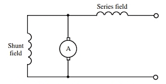
Figure 4. Schematic of a compound motor.
The series windings also carry the armature current. The winding consists of a number of heavy turns of wire. The shunt field winding consists of many turns of finer wire. Both windings are wound on the same field poles.
There are two methods used to connect these windings.
If the magnetic field on the series winding reinforces the magnetic field of the shunt winding, the motor is said to be a cumulative compound motor.
The cumulative compound motor develops high starting torque. It is used where heavy loads are applied and some variance in speeds can be tolerated. The load can be safely removed from this motor. Most compound dc motors encountered will be of the cumulative type.
If the two windings are connected to oppose each other magnetically, the motor is a differential compound motor.
The differential compound motor behaves much like the shunt motor. The starting torque is low, and it has good speed regulation if loads do not vary greatly. Consequently, this motor is not widely accepted.
Motor Starting Circuits
Armature resistance in most motors is quite low. When the motor is stopped or at low speed, very little counter emf is developed to oppose the line voltage. Therefore, dangerously high currents will flow. To protect the motor until it builds up its speed and c-emf, a current limiting resistor can be placed in series with the armature.
A simplified motor starting circuit is drawn in Figure 5. The resistance is variable. Starting from a dead stop, maximum resistance is inserted in the armature circuit. As the speed builds up, the resistance is slowly decreased. The resistance can be removed when the motor reaches full speed.
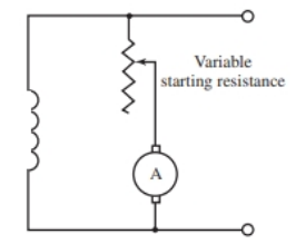
Figure 5. Simplified motor starting circuit
Example:
Using Ohm’s law, assume the armature resistance is 0.1 ohm, and the applied voltage is 100 volts. The initial armature current would be:
\[{{\text{I}}_{\text{armature}}}\text{=}\frac{\text{100V}}{\text{0}\text{.1 }\!\!\Omega\!\!\text{ }}\text{=1000 Amps}\]
This excessively high current would burn the insulation off the wires, and the motor would be destroyed.
When the motor is up to speed and c-emf has developed, then the voltage across the armature is equal to:
\[{{\text{E}}_{\text{line}}}\text{-counter }\!\!\_\!\!\text{ emf=}{{\text{E}}_{\text{armature}}}\]
If the motor develops a c-emf of 95 volts as it approaches full speed, the armature current would be:
\[{{\text{I}}_{\text{armature}}}\text{=}\frac{\text{100V-95V}}{\text{0}\text{.1 }\!\!\Omega\!\!\text{ }}\text{=50 Amps}\]
This is a safe current for this motor armature to carry. Therefore, we should start the motor with the full series resistance in the armature circuit. Then, the resistance should be gradually decreased until the motor can limit the current by its own c-emf.
Manual starters
Most manual starters have been replaced by automatic starter systems. However, some manual starters can still be found in industry. With a manual starter, the starting resistance is adjusted by hand using a lever. The lever decreases the resistance step-by-step, until the motor reaches full speed, Figure 6.
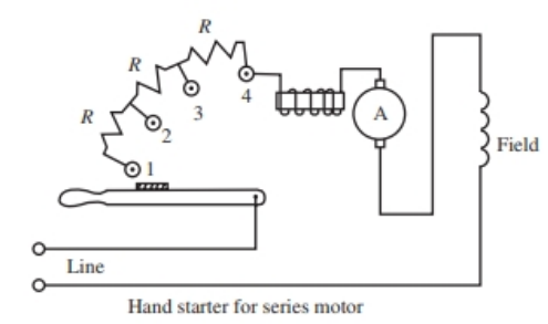
Figure 6. Typical manual step motor starter circuit
In step 1, the maximum resistance is in series. With each following step, the resistance decreases. At step 4, the lever arm is held magnetically by the holding coil, which is also in series with the circuit.
If the line voltage should fail, the lever arm will snap back to the off position, and the motor will have to be restarted. This protects the motor from an applied full voltage when the power comes back on.
Operators must use good judgment when starting a motor. They must not move the lever to the next lower resistance position until the motor has gained sufficient speed.
Automatic starters
Automatic starters remove the possibility of human error and also permit remote starting of the motor. Several devices are used. Figure 7 shows one type of automatic starting switch.
When line switch S is closed, voltage is applied to the field across the line. Voltage is also applied to the armature through R1, R2, and R3 in series with the armature contactors C1, C2, and C3. The contactors will not close until the current has decreased to a preset value.
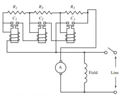
Figure 7. Circuit for an automatic motor starter.
The first surge of current in the armature circuit flows through the series coil of C1, which holds it open. As the motor increases speed and the armature current decreases, C1 contactor closes and cuts R1 out of the circuit. Similar action occurs in C2 and C3. When the motor reaches full speed, all contactors will be closed. The protective resistance is no longer needed.
Push-Button Starter
Another type of motor starter is the push-button starter, Figure 8. Motors with push-button starters are equipped with starting boxes containing push buttons marked stop and start. The circuit diagram is shown in Figure 9.
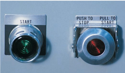
Figure 8. This type of push-button starter pulls to start and pushes to stop. There is no separate button.
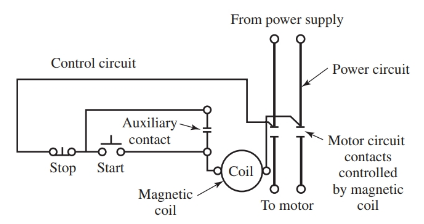
Figure 9. Schematic of a typical dc motor starter with a push-button control circuit.
This starter is a heavy-duty relay operated by momentary contact push-button switches. Look at Figure 9 as the operation of the starter circuit is explained.
1. To start the motor, the push button marked “start” is pushed closed.
a. The action of closing the start button will energize the magnetic coil through the normally closed stop button.
b. When the magnetic coil is energized, the two motor contacts and the auxiliary contact close.
c. The motor circuit contacts now supply power to the motor.
d. The auxiliary contact keeps the circuit completed to the coil so that the coil will remain energized when the start button is released. The circuit remains energized until the stop button is pushed.
2. When the stop button is pushed, the circuit to the magnetic coil is opened.
a. when the coil is no longer energized, all three contacts open.
b. Power is disconnected from the motor.
This is one of the most common motor control devices in use today.
