In this guide, we are covering DC Generator parts (components) and it’s operating (working) principle, along with figures, in detail.
A DC generator is a machine that converts mechanical energy into electrical energy by means of electromagnetic induction. DC generators operate on the principle that when a coil of wire is rotated in a magnetic field, a voltage is induced in the coil. The amount of voltage induced in the coil is determined by the rate at which the coil is rotated in the magnetic field.
When a coil is rotated in a magnetic field at a constant rate, the voltage induced in the coil depends on the number of magnetic lines of force in the magnetic field at each given instant of time. DC generators consist of field windings, an armature, a commutator, and brushes. See Figure 1.
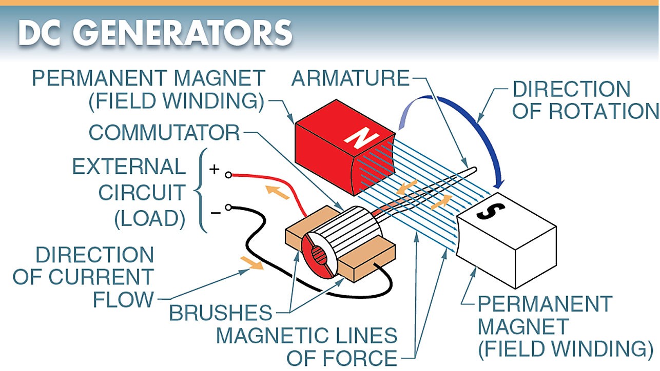
Figure 1. DC generators consist of field windings, an armature, a commutator, and brushes. They operate on the principle that when a coil of wire is rotated in a magnetic field, a voltage is induced in the coil.
Field Windings
Field windings are electromagnets used to produce the magnetic field in a DC generator. The magnetic field used in a generator can be produced by permanent magnets or electromagnets.
Permanent magnets are used in very small machines referred to as magnetos. A disadvantage of permanent magnets is that their magnetic lines of force decrease as the age of the magnet increases.
Another disadvantage is that the strength of a permanent magnet cannot be varied for control purposes.
Most generators use electromagnets, which must be supplied with current.
If the current for the field windings is supplied by an outside source (a battery or another DC generator), the generator is separately excited. If the generator itself supplies current for the field windings, the generator is referred to as self-excited. DC generators are usually self-excited.
Armatures
An armature is the movable coil of wire in a generator that rotates through the magnetic field. A DC generator always has a rotating armature and a stationary field (field windings). The rotating armature may consist of many coils. Although increasing the number of coils reduces the ripples (pulsations) in the output voltage, it is impossible to remove the ripples completely.
Commutators
A commutator is a ring made of segments that are insulated from one another. Each end of a coil of wire is connected to a segment. A voltage is induced in the coil whenever the coil cuts the magnetic lines of force of a magnetic field. See Figure 2.
The commutator segments reverse the connections to the brushes every half cycle. This maintains a constant polarity of output voltage produced by the DC generator.
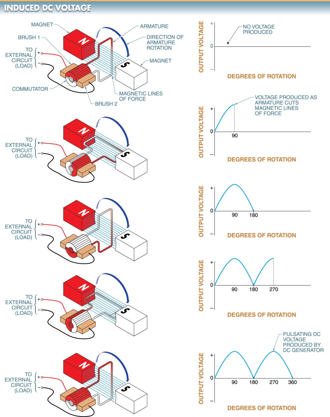
Figure 2. A voltage is induced in the coil (armature) of a DC generator when the coil cuts the lines of force of a magnetic field.
Brushes
A brush is a sliding contact that rides against the commutator segments or slip rings and is used to connect the armature to the external circuit.
Brushes are made from soft carbon (natural graphite). Brushes are softer than the commutator bars yet strong enough so that the brushes do not chip or break from vibration. One brush makes contact with each segment of the commutator.
A DC generator is designed so that the brushes ride on the different segments of the commutator each time the current is zero. Therefore, the current in the external circuit (load) always flows in one direction; however, its magnitude varies continuously.
The action of reversing the connections to the coil (armature) to obtain a direct current is referred to as commutation. The resulting output voltage of a DC generator is a pulsating DC voltage. The pulsations of the output voltage are known as ripples.
Left-Hand Generator Rule
The left-hand generator rule is the relationship between the current in a conductor and the magnetic field existing around the conductor.
The left-hand generator rule states that with the thumb, index finger, and middle finger of the left hand set at right angles to each other, the index finger points in the direction of the magnetic field, the thumb points in the direction of the motion of the conductor, and the middle finger points in the direction of the induced current. See Figure 3.
When using the left-hand generator rule, it is assumed that the magnetic field is stationary and that the conductor is moving through the field.
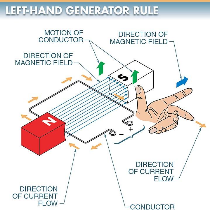
Figure 3. The left-hand generator rule expresses the relationship between the conductor, the magnetic field, and the induced voltage in a DC generator.
Tech Fact
When a DC generator is used to charge batteries, a diode can be inserted between the generator and batteries so that the current cannot flow from the batteries back to the generator.
The current flow from batteries back to a generator can occur when the generator voltage drops below the battery voltage. In this case, the current sent to the generator operates the DC generator as a motor and drains the batteries.
