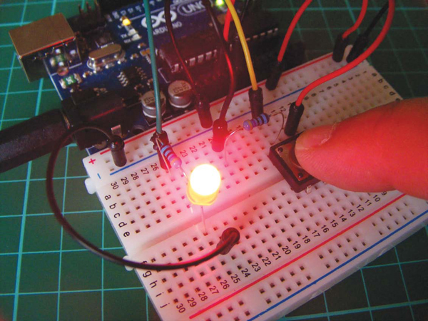
In this project, you’ll add a push-button switch to an led circuit to control when the led is lit.
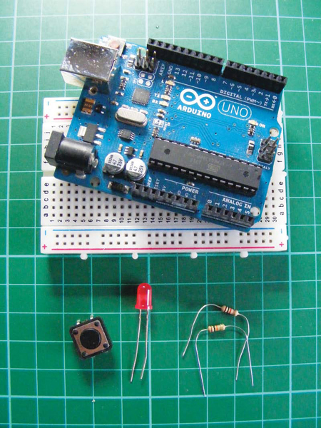
PARTS REQUIRED
- Arduino board
- Breadboard
- Jumper wires
- LED
- Momentary tactile four-pin pushbutton
- 10k-ohm resistor
- 220-ohm resistor
This project will take you through the basics of switches, which you’ll be using a lot throughout this book. Almost all electrical items use switches to turn an element on or off. There are many types of switches, and the one you’ll use now is a pushbutton (Figure 1).
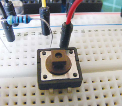
FIGURE 1: A pushbutton
HOW IT WORKS
When pressed, a pushbutton completes a circuit, turning it on. As soon as the button is released, the connection will spring back and break that circuit, turning it off. The pushbutton switch is also known as a momentary or normally open switch and is used in, for example, computer keyboards. This is in contrast to a toggle switch, which stays either on or off until you toggle it to the other position, like a light switch.
This type of pushbutton has four pins, but you generally use only two at a time for connection. You’ll use the top connections in this project, although the two unused pins at the bottom would do the same job. As Figure 2 shows, the pins work in a circuit. Pins A and C are always connected, as pin B and D. When the button is pressed, the circuit is complete.
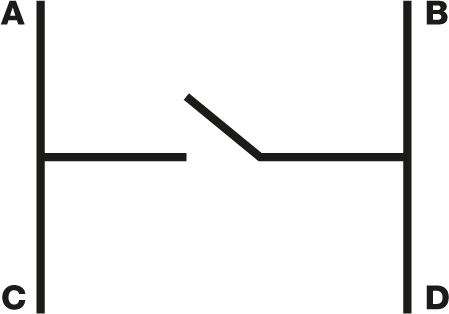
FIGURE 2: A pushbutton’s incomplete circuit
THE BUILD
1. Place your pushbutton in a breadboard, as shown in Figure 3.
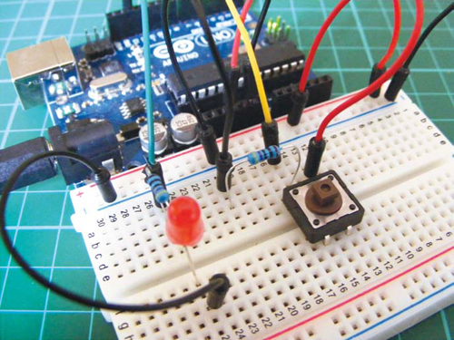
FIGURE 3: Placing your pushbutton
2. Connect pin A to one leg of a 10k-ohm resistor, and connect that same resistor leg to Arduino pin 2. Connect the other resistor leg to the GND rail, and connect the GND rail to the Arduino’s GND. Connect pin B on the switch to the +5V rail, and connect this rail to +5V on the Arduino.
| PUSHBUTTON | ARDUINO |
| Pin A | GND and pin 2 via 10k-ohm resistor |
| Pin B | +5V |
3. Add the LED to your breadboard, connecting the longer, positive leg to Arduino pin 13 via a 220-ohm resistor and the shorter leg to GND.
| LED | ARDUINO |
| Positive leg | Pin 13 via a 220-ohm resistor |
| Negative leg | GND |
4. Confirm that your setup matches the circuit diagram shown in Figure 4, and then upload the code in “The Sketch” given below.
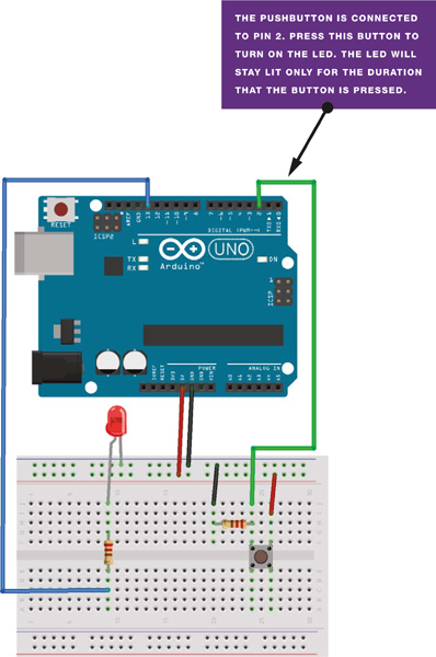
FIGURE 4: Circuit diagram for the pushbutton-controlled LED
THE SKETCH
In this sketch, you assign a pin for the pushbutton and set it as INPUT, and a pin for the LED and set it as OUTPUT. The code tells the Arduino to turn the LED on as long as the button is being pressed (completing the circuit) and to keep the LED off when the button is not being pressed. When the button is released, the circuit breaks and the LED will turn off again.