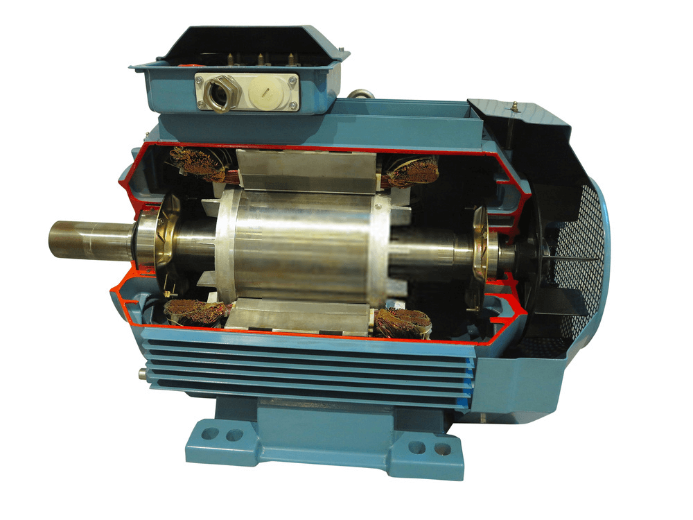
For its operation, a three-phase induction motor is dependent on a rotating magnetic field being established by the AC windings. The three separate windings are installed in the stator at 120°E intervals to one another and provide a fixed number of poles for each phase. This is shown diagrammatically in Figure 1(a) for one phase of a two-pole machine.
Figure 1(b) shows the three phases in relation to one another, giving a total of six poles. Phase A is drawn as a solid line, phase B as a dotted line and phase C as a dashed line. Note that this sequence is carried through for the explanation and applies to the current waveforms, the magnetic fields and the phasors.
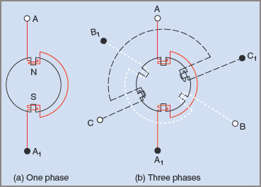
Figure 1 Polarities and connections in a two-pole, three-phase induction motor
Assumption
In the following explanation for the production of a rotating field, one assumption has been made as a reference: that winding ends A, B, C, when connected to a positive source of voltage, makes the adjacent iron core a north magnetic pole. From this it will follow that the opposite poles become south magnetic poles. These details are also shown in Figure 1(a). If the current flow is reversed, then the magnetic poles are also reversed.
With the three windings connected in star configuration by joining ends A1, B1, C1 together, and the ends A, B, and C connected to a three-phase supply, the phase currents IA, IB and IC are 120°E out of phase with one another. This is shown in Figure 2.
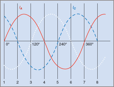
Figure 2 Waveform diagram showing three-phase currents at 120°E
Because each current is alternating, each pair of poles sets up a magnetic flux that continually changes from one polarity to the other. Note that although the flux set up by phase A in Figure 1(b) alternates in the direction in the diagram, it does not rotate in any way. It simply varies in strength and direction in the vertical plane.
Similarly, a pulsating flux is also established by the other two phases, giving a total of three magnetic fluxes that combine into one resultant flux. This flux rotates at synchronous speed.
At reference position 1 in Figure 2, the current IA is zero and no flux is produced by the winding A–A1. Current IB is negative and so will produce a south pole at B and a north pole at B1. Current IC is positive so will produce a north pole at C and a south pole at C1. Because currents IB and IC are equal, the two magnetic fields are equal in strength. The directions of these fields are shown in Figure 3(a). In the accompanying phasor diagram the addition of these two fields is shown, giving a resultant instantaneous field ΦR.
Figure 3 Resultant flux produced at positions indicated from Figure 2
At position 2 in Figure 2, IA is positive, IB is still negative while IC is zero. This produces a north pole at A, a south pole at B and nothing at C. This is shown in Figure 3(b) together with the phasor diagram showing the addition of the phasors to give the resultant instantaneous magnetic field.
Since all coils have an equal number of turns, the relative strengths of the magnetic fields can be gauged by measuring the vertical heights of the current waveforms at the positions indicated by the reference number. In this instance the direction of the resultant magnetic field has shifted 60°E clockwise from that in position 1.
If drawn to scale it can also be shown that the length of the resultant has remained constant, indicating that the field strength has remained constant.
At position 3 (Fig. 2), IA is positive, producing a north pole at A and a south pole at A1, IB is zero and IC is negative, producing a south pole at C and a north pole C1. These fields are drawn in Figure 3(c) together with their phasors. The resultant field has rotated a further 60°E in a clockwise direction. (There is a 60°E difference between all the numbered positions in Fig. 2.)
For each of the numbered positions, the resultant field rotates a further 60°E in a clockwise direction. For one complete cycle of current (360°E) the resultant magnetic field rotates 360°E.
Rate of Rotation and Factors Affecting It
By comparing Figures 2 and 3 it can be seen that for the time intervals of 60°E between positions 1, 2 and 3 the resultant field rotates an equal amount around the stator. For a complete cycle of AC, a two-pole field rotates one complete revolution around the stator. The synchronous speed of the magnetic field in revolutions per minute can be determined from the frequency of the supply.
Example 1
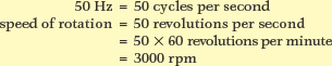
A two-pole machine is connected to a 50 Hz supply. Find the speed at which the magnetic field rotates around the stator.
With a four-pole machine, 360°E represents one-half of a full revolution of the stator field, and the speed of rotation of the field is consequently halved. Similarly, the speed of field rotation for a six-pole machine is reduced to one-third that of a two-pole machine. In each case the speed is usually expressed in revolutions per minute, whereas the frequency is in hertz (cycles per second). The speed in revolutions per minute can be found from the following formula:
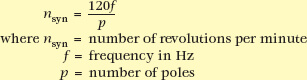
The speed n of the rotating magnetic field is called the synchronous speed of the motor. The synchronous speeds of common sizes of motors at a frequency of 50 Hz are given in Table 5.1 below.
Table 1 Speed of the Rotating Field in an Induction Motor for Various Number of Poles
| Poles | 2 | 4 | 6 | 8 | 10 | 12 |
| Synchronous speed (rpm) | 3000 | 1500 | 1000 | 750 | 600 | 500 |
Direction of Rotation and Reversal in Three Phase Induction Motor
The direction of rotation of a rotating field depends on the phase sequence of the three currents flowing through the windings. In Figure 4(a), the three supply lines R, W and B are connected to terminals A, B and C of the motor. The resultant magnetic field rotates clockwise.
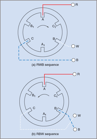
Figure 4 Phase sequence and field rotation in an induction motor
In Figure 4(b), the supply lines to phases B and C have been changed over and, using the procedure from the previous section, it can be shown that the rotation of the magnetic field is reversed. That is, the direction of rotation of the field can be controlled by interchanging any two supply lines to the motor. Above, it is shown that the rotation of a three-phase induction motor is in the same direction as that of the rotating field.
