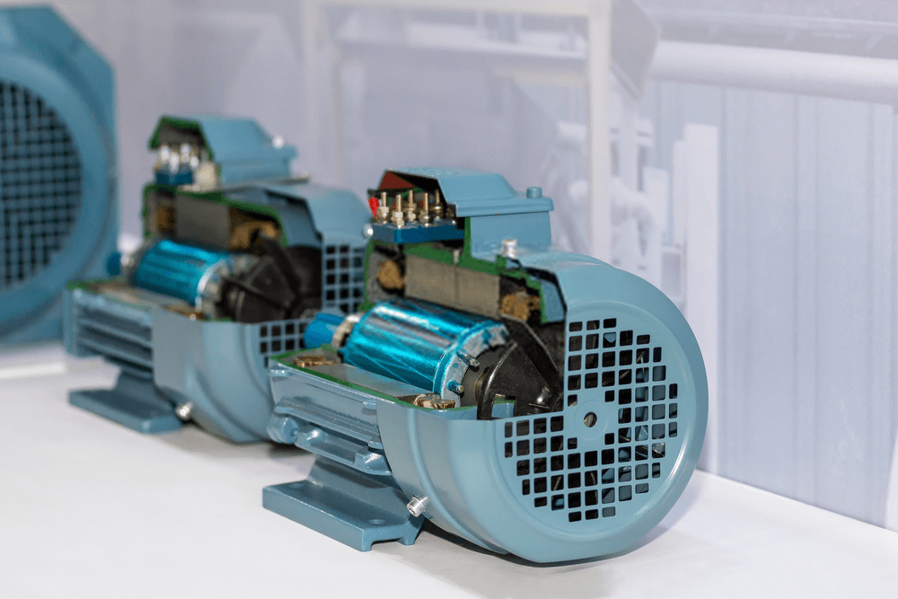
Like all motors, a three-phase induction motor contains a stator (the stationary part) and a rotor (which rotates). Each contains electrical windings that carry current and thus creates a magnetic field. The interaction of the magnetic fields creates the torque that rotates the rotor and the load. Figure 1 demonstrates a three-phase induction motor view.
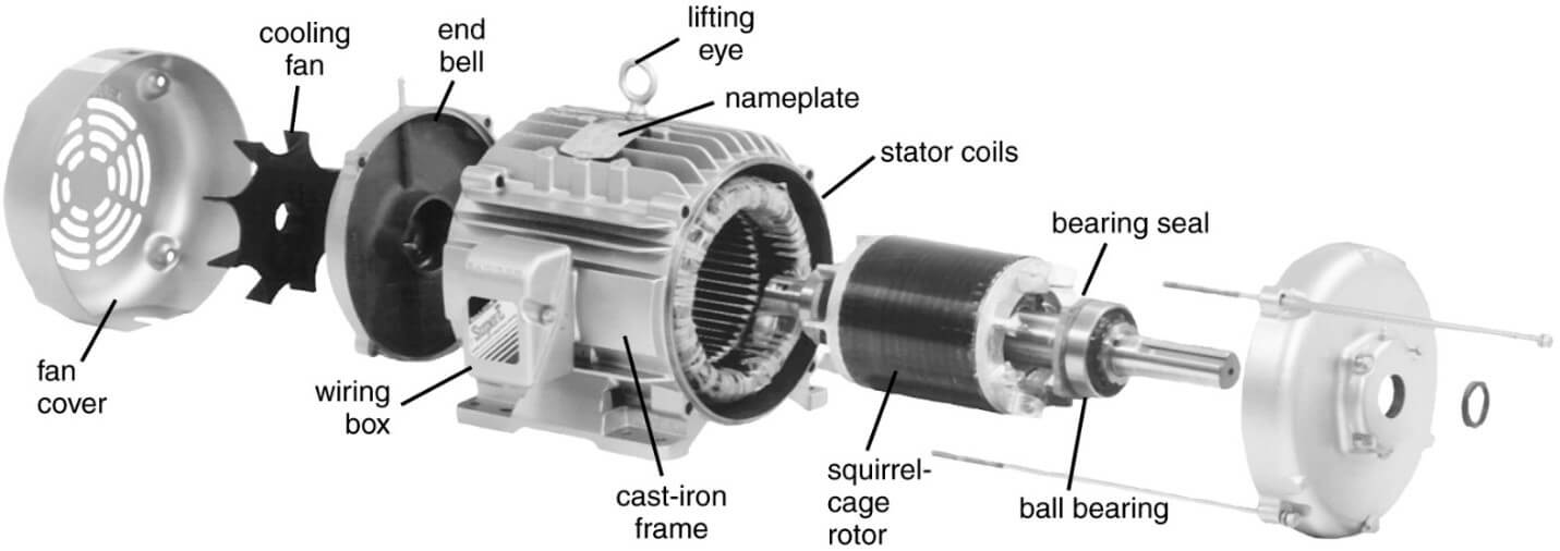
Figure 1: Exploded view of a three-phase induction motor construction: 1. Fan cover, 2. Cooling fan, 3. End bell, 4. Lifting eye, 5. Nameplate, 6. Stator kcoils, 7. Bearing seal, 8. Ball bearing, 9. Squirrel-cage rotor, 10. Cast-iron frame, 11. Wiring box
Stator
The laminated stator core is made from stamped sheet steel with slots on the inner surface. Figure 2 shows stator (and rotor) laminations. Three identical windings are laid out in a sequential series of overlapping coils.
In motors of higher power ratings, the stator slots are of the open type to allow the insertion of the large pre-shaped and insulated coils, but in smaller sizes the slots are partially closed to reduce the air gap as much as possible.
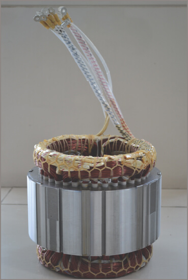
Figure 2 Induction Motor Laminated stator
The stator core is fixed into the motor frame, which serves to carry the bearings that support the rotor, to protect the coils and to provide a means by which the motor can be mounted to the machinery it is to drive.
The motor frame takes various forms, depending on the conditions under which the motor will operate. This can vary from open frame through to submerged pump motors.
Rotor
Squirrel Cage Rotor
The rotor of an induction motor consists of a shaft (spindle) with bearings, laminated iron core and rotor conductors. The most common type of construction is that with rotor bars in the lamination slots rather than a winding.
The rotor bars pass through the rotor via holes punched in the laminations when they are pressed. The ends of the rotor bars are short-circuited at each end by a solid conducting ring, often made of a copper ring brazed or fusion welded to copper rotor bars.
For small to medium motors they may be cast in one piece out of aluminum usually including cast fins for creating air movement. The rotor windings, if shown without the laminations, resemble a metal cage giving rise to the often-used name ‘squirrel cage’ rotors, although the standards refer to them simply as ‘cage’ rotors.
Figure 3 shows a cast aluminum squirrel cage rotor with end fins. The photograph also shows skewed conductors in the rotor which means that the conductors are at an angle to the axis of the rotor. Skewed conductors cause a smoother power transfer to the rotor causing less vibration and a steady acceleration during starting.
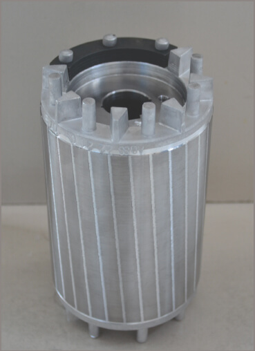
Figure 3 Squirrel cage rotor
Varying the physical design features of the bars affects motor performance. Embedding the bars deeper into the rotor, for example, increases the inductance and gives a lower starting current but creates a lower pull-out torque. This type of rotor is then restricted to loads requiring low starting torques, such as centrifugal pumps.
A side section of a complete three-phase induction motor is shown in Figure 4.
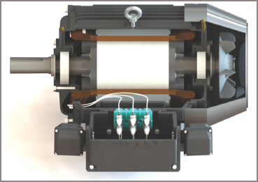
Figure 4 Side-section of a three-phase induction motor
Wound Rotor
The wound rotor is fitted with insulated windings, similar to the stator winding and having the same number of poles. The three phases are connected in star configuration with the ‘Y’ point connected on the rotor, and the three phases terminated at one end of the rotor at three slip-rings. (See Figure 5 for a typical wound rotor.)
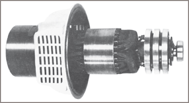
Figure 5 Typical wound rotor induction motor
The slip-rings are connected by means of brushes to an external star-connected variable resistance, as in Figure 6 overleaf.
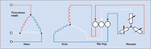
Figure 6 Wound rotor with starting resistance
This rotor rheostat provides the means of increasing the resistance of the rotor circuit during starting, thereby producing a higher starting torque at a lower starting current. As the speed increases, the external resistance is gradually reduced, lowering the rotor circuit resistance as the rotor reactance decreases.
Under operating conditions, the variations in rotor circuit resistance provide a means of controlling the speed of the motor over a small range. An increase in resistance results in a reduction in speed and torque and also produces a loss in efficiency due to the I2R losses in the rheostat.
The wound-rotor motor is more expensive than the squirrel cage motor, owing to the cost of manufacture of the wound rotor. It also has a higher starting torque and lower starting current, but poorer running characteristics than the squirrel cage motor and higher maintenance needs.
Motor Enclosures
The conditions governing the actual installation of an induction motor are normally beyond the control of the motor manufacturer. As a result, the motor is manufactured in various enclosures.
A motor driving a compressor for a refrigerated display cabinet, for example, may operate under such clean and dry conditions that the motor enclosure need only provide a mounting for the bearings and a means for fixing the motor in a horizontal plane. At the same time the enclosure provides mechanical protection against accidental spillage and enables cooling air to circulate freely through the motor windings.
Compare this situation with a water turbine pump used for irrigation purposes. In most cases the motor is mounted vertically at the bore head and is given no protection from the weather. The motor needs to be totally enclosed to prevent the entry of water, and cooling is by means of heat transfer through the motor housing.
The air sealed within the motor housing is circulated by an internal fan, so transferring the heat generated by the windings to the housing. This heat is then transferred to the atmosphere by a second fan circulating free air across the outside of the motor housing.
Terminal Block Arrangements
Squirrel Cage Motors
Most three-phase induction motors have both ends of the three windings brought out to a six-terminal block. The only exceptions are small dedicated-purpose motors that can be started directly on line in either star or delta configuration at all times. These small three-phase motors have only three terminals (not including the earth terminal).
By custom and some attempts at standardization, the phase ends are brought out to terminals in one of two possible arrangements. In Figure 7(a) the more usual arrangement is shown, while Figure 7(b) illustrates an alternative system of connections.
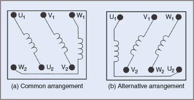
Figure 7 Three-phase induction motor terminals
The intent is to standardize connecting arrangements for personnel installing the motor or reconnecting it after maintenance. To connect a motor in either star or delta configuration, winding ends are bridged (see Figure 8).
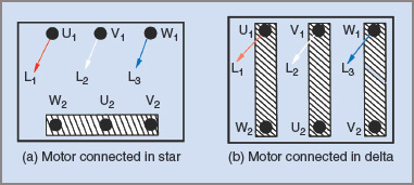
Figure 8 Bridging connections in a three-phase induction motor terminal block
The points to note are:
| 1. | Individual phase ends are not connected to terminal pairs but are offset (see Figure 8). |
| 2. | Connecting a motor in star configuration means that the windings have only 58 per cent of the line voltage applied to them. |
| 3. | In star configuration, one bridge couples all three corresponding ends of each winding. |
| 4. | The bridge can be placed across the beginnings of the phase windings instead of the ends as shown. The lines are connected to the opposite ends to the bridge. |
| There is no alternative option for the bridges when connecting a motor in delta configuration. Each bridge connects to line voltage. | |
| 6. | While bridges or shorting strips are shown in Figure 8, it might be necessary to remove the bridges so that all six ends of the windings can be connected to a starter, for example, a star–delta starter. |
Wound-Rotor Motors
With wound-rotor motors it is common to connect the stator windings internally in either star or delta configuration as required—usually delta. The terminal block will still have six terminals because the three appropriate ends of the rotor windings are connected in star configuration internally and the other ends brought out via slip-rings to the terminal block.
It is usual to identify them in some way, such as separating them from the line terminals of the stator windings or using a different type of terminal connector. Care should be taken to observe that line voltages are not connected to the rotor terminals.
- You May Also Read: Three-Phase Induction Motor Torque-Speed Characteristics
