Motor protection is important to any motor system. Most motor protection involves safety devices installed in the power lines that feed the motor. These devices protect more than just the motor. They protect the load and any other device connected in the motor system.
Motor Installation and Protection
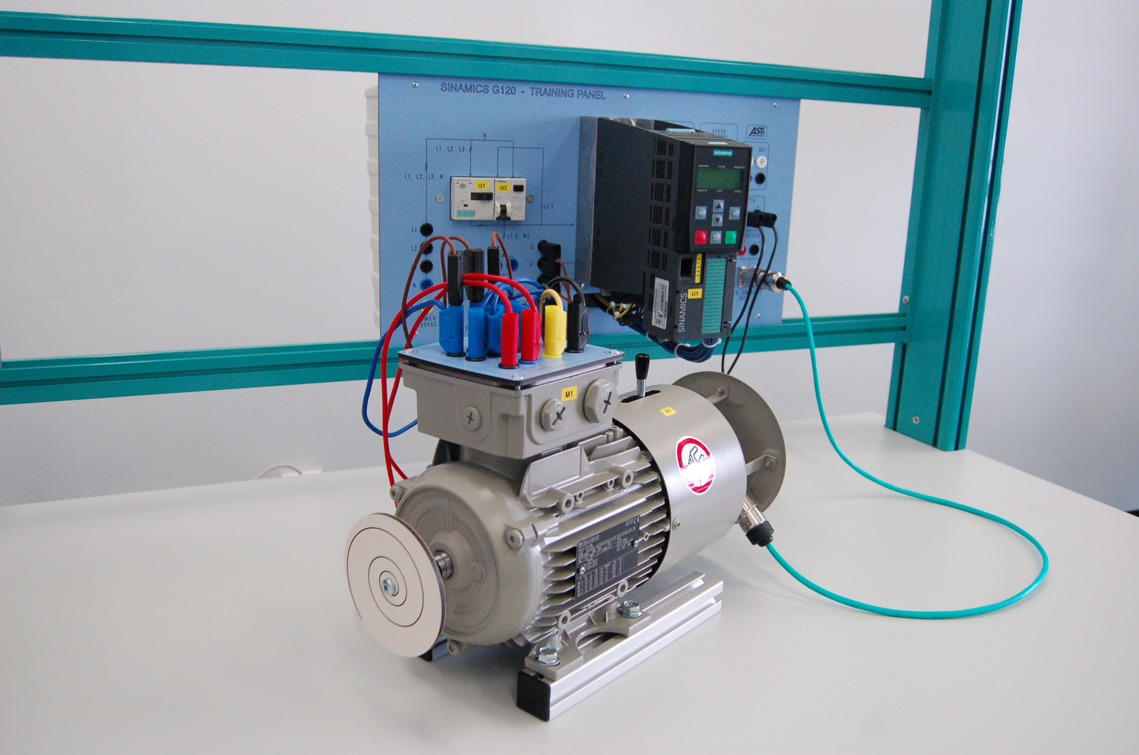
Unless the motor being used is very small, motors are installed with dedicated lines. A dedicated line means that the circuit is used for only one purpose. For a proper installation of a motor, two forms of protection are needed in this dedicated line—branch circuit protection and running protection. See Figure 1.
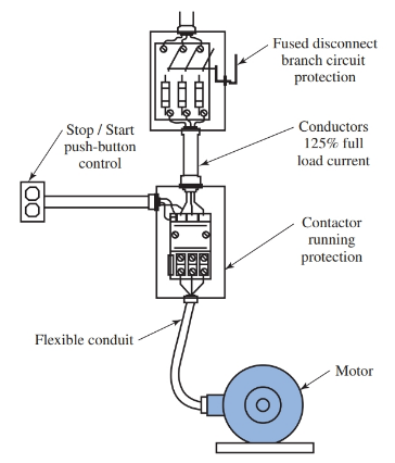
Figure 1. Typical motor installation showing locations of running protection and branch circuit protection.
Branch circuit protection means that a fuse or breaker is installed to protect the circuit feeding the motor. This fuse or breaker can be set to trip if the current exceeds anywhere from 150 percent to 500 percent of the motor’s full-load current.
The full-load current of a motor is the current the motor is expected to draw while it is under full mechanical load.
The second form of protection is called run protection. Run protection protects the motor from excessive heat damage or fire while it is in a normal mode of operation.
Run protection is a necessity since only a slight mechanical overload to a motor will, over a period of time, cause damage or fire. Running protection must be closely sized to a motor’s service factor. All motors have a service factor.
The service factor of a motor is its ability to withstand or avoid damage from an overload condition. The service factor is based on a percentage of a motor’s normal current under full load condition.
To interpret a service factor, subtract one from the number and multiply the remainder by 100. This gives you the percent overload a motor can handle.
For example, if a motor has a service factor of 1.25, it can safely withstand a 25 percent overload. A motor with a 1.15 service factor can withstand a 15 percent overload, and a motor with a 1.0 service factor can withstand no overload.
Electric Motor Failure
Most ac motors are of simple design and, unless brushes are used, require very little maintenance. However, motors will eventually fail. There are a few faults that account for most motor failure.
Excessive bearing wear
The most common cause of motor failure is excessive bearing wear. Some bearings are sealed and do not require maintenance, while others require periodic lubrication. Dry motor bearings cause friction, heat up, and wear down rapidly.
In a motor, there is very little clearance between the stator and rotor. As the bearings wear down, the rotor will begin dragging on the stator. Usually this causes a loud roar or high, shrill whining sound as well as excessive vibration. The worn bearings cause an excessive load on the motor and cause it to go into an overload condition.
Mechanical overload
Another cause of motor failure for small ac motors is mechanical overload. An example of mechanical overload is when a power tool is used continuously under severe mechanical conditions. The tool heats up until the temperature exceeds the temperature rating of the stator’s insulation.
Once this occurs, the windings are irreversibly damaged. The damage can be so severe as to produce a short between the windings or to the iron laminations.
Single-phasing condition
Three-phase motors are often exposed to another damaging situation called a single-phasing condition. A single-phasing condition occurs when the power supply to the three-phase motor loses one of its three lines due to an open or blown fuse.
If the motor is running at the time the loss occurs, it will continue to run. However, there will be an increase in current in the two remaining motor windings. Unless the overload protection trips the relay coil in the starter, this current increase will damage the motor.
Small motors can have a thermo device inserted in the motor windings that will open when excess heating occurs. This device offers some protection for a motor experiencing mechanical overload or a single-phasing condition. If this type of running protection is included as a part of the motor, the data plate will indicate that the motor is thermo protected.
Locked rotor condition
The most severe damage occurs to a motor when it has a locked rotor condition. A locked rotor condition is when the motor is energized, but the rotor is not turning.
A mechanical failure in the system to which the motor is connected can cause this condition. When locked rotor occurs, the current in the windings is extremely excessive and can severely damage the motor windings.
Low voltage
Another common cause of excessive motor current is low voltage. Under a low voltage condition, a motor will maintain its horsepower output rating until the low voltage becomes so severe that the rotor locks. This low voltage condition causes excessive current in the windings while the motor is under mechanical load.
Remember, when checking for low voltage conditions, the motor must be under mechanical load. Otherwise, the voltmeter readings will not be accurate. As current increases, so does the voltage drop along a conductor. As the mechanical load on a motor increases, so does the current. As the current increases, so does the voltage drop at the motor.
Look at the illustrations in Figure 2. Many burnt winding patterns can reveal why a motor failed.
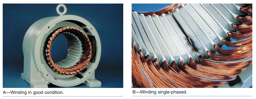
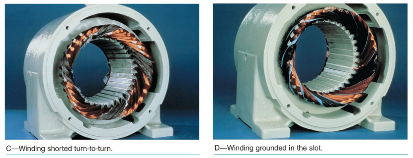
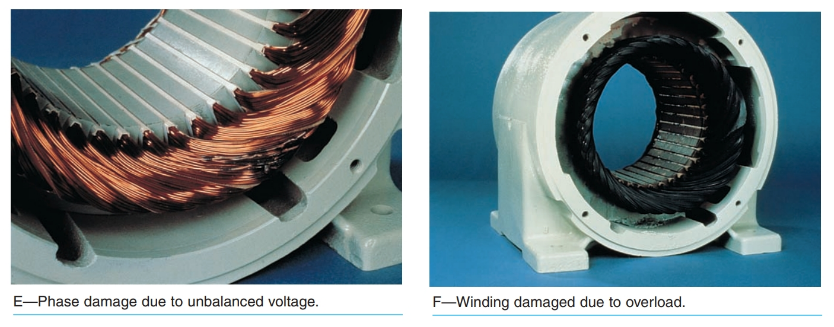
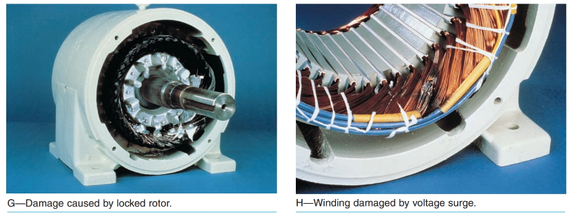
Figure 2. Figure A shows a motor with windings in good condition. Figures B through H show motor windings damaged through a variety of causes. Can you explain the patterns of the scorch marks by their causes? (Electrical Apparatus Service Association, Inc.)
Troubleshooting Electric Motors
The most useful tool when troubleshooting motors is the clamp-on ammeter. The clamp-on ammeter operates using the transformer principle of induction.
The ammeter clamps around the line to be read, Figure 3. The clamp is the primary coil and the secondary coil is inside the meter housing. The current in the line being measured produces a flux field that cuts across the clamp. This generates an emf that is measured by the meter movement.
The clamp-on ammeter is used only for ac circuits. Its greatest advantage over other forms of ac ammeters is that the circuit does not have to be opened to connect the meter in series with the circuit.
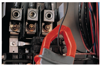
Figure 3. Clamp-on ammeter in use. (Fluke Corp.)
A simple ammeter reading can tell you a lot about the condition of the motor. As a motor’s windings break down, they will draw more current in the lines to the motor. This will show up on the ammeter.
Another quick check is to measure and compare all three lines of a three-phase motor. The three lines should have identical current values. Any deviation from a near perfect match means the motor windings are breaking down.
Another useful tool is the megohmmeter. As the name indicates, the megohmmeter is a type of ohmmeter that measures resistance in the millions of ohms range. This meter generally uses a much higher operational voltage than a standard ohmmeter.
A standard ohmmeter uses only nine volts in the ohmmeter circuit. The standard type of meter would not have sufficient voltage to detect a short or ground in a motor that operates at a higher voltage such as 480 volts.
