
After studying this article, you will be able to:
- Explain how mechanical energy can produce electrical energy.
- State Lenz’s law.
- Discuss the difference between direct current and alternating current.
- Explain the construction and function of an Electric generator.
In 1831, scientist Michael Faraday wondered: If electricity produces magnetism, can magnetism produce electricity?
Magnetic Induction
Based on his research, Faraday learned that magnetism could, in fact, produce electricity. He found that moving a conductor through a magnetic field induced (brought about) a voltage in the conductor. This is known as magnetic induction. Three things are required to induce a voltage. There must be:
• A magnetic field.
• A conductor.
• Relative motion between the field and conductor.
See Figure 1.
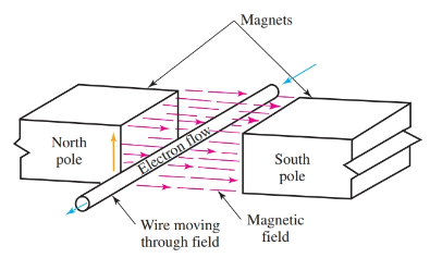
Figure 1. Magnetic induction. Passing a conductor through a magnetic field displaces electrons in the conductor. The electrons move through the conductor
In the following experiment, you can watch the principles of magnetic induction at work. Refer to Figure 2.
- A coil is attached to a galvanometer. A galvanometer is a meter that measures the size and direction of small electric currents.
- A permanent bar magnet is placed in the hollow coil.
- As the magnet moves into the coil, the needle on the meter shows current flowing in one direction.
- As the magnet is taken out of the coil, the needle shows current flowing in the other direction.
- When the magnet is still, no current is produced.
- The same meter movements are produced when the magnet is held still and the coil is moved over the magnet.
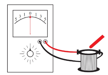
Figure 2. Use a galvanometer, a coil, and a magnet to observe the principles of magnetic induction.
Figure 3 shows the action of a coil turning in a magnetic field.
- In position A, the coil top moves parallel to field of magnetism. No voltage is produced.
- In position B, both sides of the coil are cutting the field at right angles. The highest voltage is produced at this right angle.
- Position C is like position A, the voltage drops to zero.
- In position D, the coil is again cutting the field at right angles, where the highest voltage is induced. However, in position D the voltage is in the opposite direction of that produced at position B.
The curve in Figure 3 shows the voltage induced in the one turn of the coil.
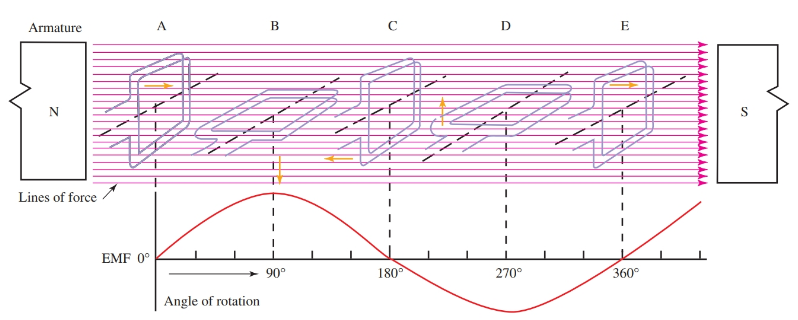
Figure 3. Step-by-step development of induced voltage during one revolution of a coil
How this is induced voltage created? Figure 4 shows single conductors passing through a magnetic field. At the top, the conductor is pushed downward through the magnetic field. On the bottom, the conductor is pushed back upward. The current generated is shown by the arrows. In each case, the induced current in the conductor forms a magnetic field around the conductor.
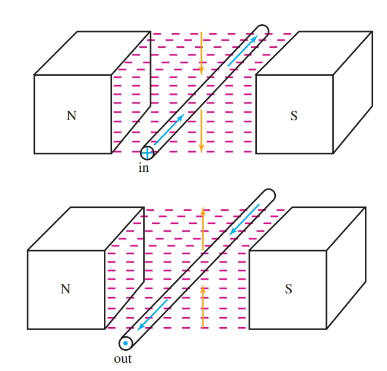
Figure 4. The direction of the current through a conductor is determined by the direction the conductor cuts across a magnetic field.
The field around the conductor opposes, and is repelled by, the fixed field. This phenomenon is stated in Lenz’s law: The polarity of an induced electromagnetic force is such that it produces a current. The magnetic field of this current always opposes the change in the existing magnetic field.
More simply, Lenz’s law says that: the field induced around the conductor is opposed by the existing field. Therefore, in order to produce electricity, some form of mechanical force must be applied to overcome this opposition and turn the coils. For example, water and steam supply the mechanical force to turn turbines in large power plants.
The strength of the induced voltage in a rotating coil depends on:
- The number of magnetic lines of force cut by the coil.
- The speed at which the conductor moves through the field.
When a single conductor cuts across 100,000,000 (108) magnetic lines in one second, one volt of electrical pressure is produced. This voltage can be increased by winding the armature with many turns of wire, by increasing its speed of rotation, or both. This link can be expressed by the mathematical equation:
\[E=\frac{\phi \times N}{{{10}^{8}}}=\frac{\text{magnetic Flux Lines}\times \text{Revolution Per Second}}{\text{Number of Flux Lines per Volt}}\]
Where E equals the induced voltage, ϕ equals the lines of magnetic flux, and N equals revolutions per second.
For example, if a fixed magnetic field consists of 106 lines of magnetic flux and a single conductor cuts across the field 50 times per second, the induced voltage would equal:
\[E=\frac{{{10}^{6}}\times 50}{{{10}^{8}}}=50\times {{10}^{-2}}=0.5V\]
One half volt is produced by this generator.
DC versus AC
Direct current (DC) flows in only one direction through a conductor. If the flow of electrons is constant it is called pure direct current. If the flow is intermittent it is known as pulsating direct current. See Figure 5.
Alternating current (AC) flows in alternating directions (back and forth) through a conductor within a given time period. Alternating current is shown at the bottom of Figure 3. This curve is called a sine wave.
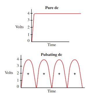
Figure 5. Graphs showing pure dc and pulsating dc.
Electric Generator Construction
A generator is a device that changes mechanical energy into electrical energy. You saw this change in Figure 3. The revolution of the coil (mechanical energy) was changed to induced current (electrical energy). This action is an example of a very simple electric generator.
The electricity produced in this simple electric generator is not very useful because it is not powerful enough to do work. The system requires some improvements.
A stronger magnetic field can be created for this improved generator by replacing the permanent magnets with electromagnets. Field coils can be placed over pole pieces or shoes that are fastened to the steel frame or generator case.
The revolving coil, or armature, is suspended in the case resting on the proper bearings. The single coil is replaced by wire coils of many turns on the armature. The rotating armature is connected to the outside circuit through commutators or slip rings.
The commutators and slip rings touch brushes in the outside circuit. Generator brushes are constructed mainly of simple, soft carbon.
The major difference between an AC generator and DC generator is the use of slip rings in the ac generator and the use of a commutator (split ring) in the dc generator. Both slip rings and split rings provide the electrical current connections from the armature to the generator load circuit.
Two slip rings are used on AC generators. The slip rings provide a mechanical means of maintaining the connection between the armature circuit and the outside circuit. See Figure 6.
In the AC generator, the slip rings are in constant contact with the brushes. Since an alternating current is produced in the armature circuit, the outside circuit is also AC. Both the DC generator and AC generator produce an AC current in the armature windings.
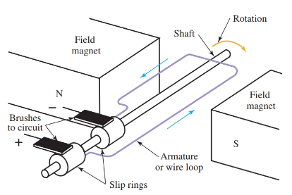
Figure 6. Simple AC generator. A wire loop carries the induced current. Electrons flow out one brush, through the circuit, and back in through the other brush
When DC is desired in the outside circuit, a set of commutator segments and a set of brushes are used. A commutator, or split ring, is a device that reverses electrical connections and is used on DC generators. See Figure 7.
The mechanical connection between the outside circuit and the armature constantly changes because of the brush and commutator connections. The action of the commutator and brushes maintains a constant flow in one direction toward the outside circuit. Study Figure 8 closely to see how the direction of the current is maintained in the outside or load circuit. The drawings show the action of the commutator and brushes. The polarity of the brushes is constant.
The polarity of the slip rings in the AC generator, Figure 6, changed as the direction of the current changed with each half revolution. In the DC generator, the alternating current in the armature is changed to a pulsating direct current.
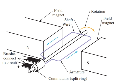
Figure 7. Simple DC generator.
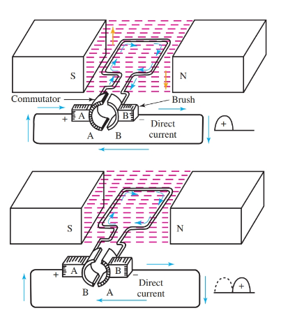
Figure 8. The commutator changes the alternating current in the armature to a pulsating direct current in the outside circuit.
Note that the current in the outside circuit of the dc generator always flows in one direction. The output of the generator is shown in Figure 9. The voltage rises and falls from zero to a maximum to zero, but always in the same direction.
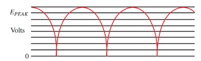
Figure 9. Generator output in volts.
Follow the action in Figure 8. Brush A is in contact with commutator section A, and brush B is in contact with commutator section B. The first induced wave of current flows through the armature out of brush B, around the external circuit and into brush A, completing the circuit.
When the armature revolves one-half turn, the induced current will reverse its direction. However, the commutator sections have also turned with the armature. The induced current flowing out of commutator section A is now in contact with brush B. This current flows through the external circuit to brush A into commutator section B, completing the circuit.
The current flows through the external circuit in the same direction both times. The commutator has acted as a switch. It reversed the connections to the rotating coil when the direction of the induced current was reversed.
The current in the outside circuit is pulsating direct current. The output of this generator is not a smooth direct current. The weakness of pulsating DC can be improved two ways. The number of rotating coils on the armature can be increased and commutator sections can be supplied for each set of coils.
To help you understand how the coils are added to the armature, examine Figure 10. Each coil has its own induced current. As the current starts to fall off in one coil, it is replaced by an induced current in the next coil.
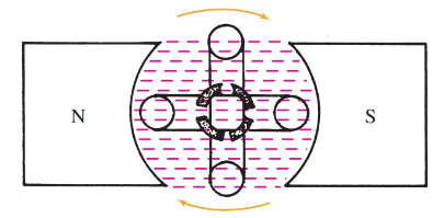
Figure 10. A simple electric generator with two coils at right angles to each other. They are rotated in magnetic field.
The current is created as the coils cut across the magnetic field. A graph of the output from the generator of Figure 10 is shown in Figure 11. It is still a pulsating current. However, the pulses come twice as often and are not as large.
The output of the two-coil generator is much smoother. By increasing the number of coils, the output will closely duplicate a pure direct current with only a slight ripple variation.
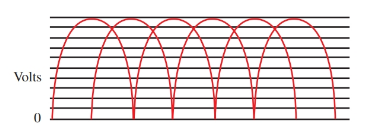
Figure 11. Output of the generator in Figure 10.
Electric Generator Losses
All of the mechanical power used to turn the generator is not converted into useful electrical power. There are some losses.
I2R losses
You will recall that all wires have some resistance. The size of this resistance depends on the wire size, material, and length. Resistance uses power.
In the generator coils there are many feet of copper wire. The resistance of this wire must be overcome by the induced voltage. Voltage used in this manner supplies nothing to the external circuit. It only creates heat in the generator windings. Power loss in any resistance is equal to:
$P={{I}^{2}}R$
Of special concern is the fact that power loss increases by the square of the current. To be specific, if the current in the generator doubles, the power loss is four times (22) more.
The limiting factor in generator output is usually the wire size and current-carrying capacity of the armature windings.
Losses resulting from resistance in the windings are called copper losses or I2R losses.
Eddy currents
The armature windings in the generator are wound on an iron core, which is slotted to hold the coils. Like a conductor, as the solid iron core rotates, it induces voltages, causing an alternating current to flow in the core. This alternating current is known as an eddy current. It produces heat, which is a loss of energy. To reduce this loss, cores are made of built up thin sections or laminations, Figure 12.
Each section is insulated from the next section by lacquer or, at times, only oxide and rust. These laminations reduce the voltage in the core and increase resistance to the power draining eddy currents.
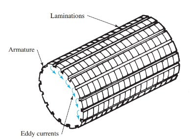
Figure 12. Lamination of the metal core of an armature reduces the flow of eddy currents.
Eddy currents increase in the core as the speed of rotation increases or the field density increases. When iron cores are used in rotating machines and transformers, they are laminated to reduce eddy current losses.
Hysteresis
The third loss occurring in a generator is called hysteresis loss. Hysteresis is also called molecular friction.
As the armature rotates in the fixed magnetic field, many of the magnetic particles in the armature core remain lined up with the fixed field. These particles then rotate against those not lined up with the field. This rotation causes internal friction between the magnetic particles and creates a heat loss.
Generator manufacturers now use a silicon steel which has a low hysteresis loss. Annealing the core (a heat process) further reduces this loss.
