In this guide, we have covered AC Generator parts (components) along with their figures (images) in detail.
Generators convert mechanical energy into electrical energy by means of electromagnetic induction. AC generators, also referred to as alternators, convert mechanical energy into AC voltage and current. AC generators consist of field windings or permanent magnets, an armature, slip rings, and brushes. See Figure 1.
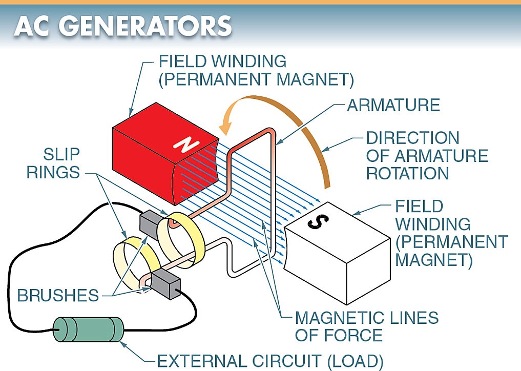
Figure 1. AC generators consist of field windings, an armature (coil), slip rings, and brushes
Field Windings
A field winding is an electromagnet used to produce the stationary magnetic field in a generator. The magnetic field in a generator can be produced by permanent magnets or electromagnets. However, most generators use electromagnets, which must be supplied with current. See Figure 2.
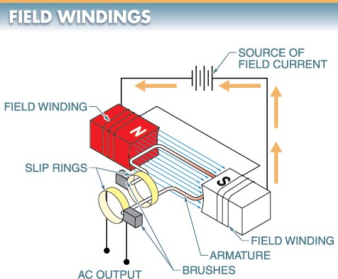
Figure 2. Field windings are used to produce the stationary magnetic field in a generator.
Armature
An armature is the movable coil of wire in a generator that rotates through the magnetic field. The armature may consist of many coils. The ends of the coils are connected to slip rings.
Slip Rings
Slip rings are metallic rings connected to the ends of the armature and are used to connect the induced voltage to the brushes. When the armature is rotated in the magnetic field, a voltage is generated in each half of the armature coil.
Brushes
A brush is a sliding contact that rides against the commutator segments or slip rings and is used to connect the armature to the external circuit.
AC generators are similar in construction and operation to DC generators. The major difference between AC and DC generators is that DC generators contain a commutator that reverses the connections to the brushes every half cycle. This maintains a constant polarity of output voltage produced by the generator. AC generators use slip rings to connect the armature to the external circuit (load). The slip rings do not reverse the polarity of the output voltage produced by the generator. The result is an alternating sine wave output.
Armature Function
As the armature rotates, each half cuts across the magnetic lines of force at the same speed. Thus, the strength of the voltage induced in one side of the armature is always the same as the strength of the voltage induced in the other side of the armature.
Each half of the armature cuts the magnetic lines of force in a different direction. For example, as the armature rotates in the clockwise direction, the lower half of the coil cuts the magnetic lines of force from the bottom up to the left, while the top half of the coil cuts the magnetic lines of force from the top down to the right. Therefore, the voltage induced in one side of the coil is opposite to the voltage induced in the other side of the coil. The voltage in the lower half of the coil enables current to flow in one direction, and the voltage in the upper half enables current to flow in the opposite direction.
However, since the two halves of the coil are connected in a closed-loop, the voltages add to each other. The result is that the total voltage of a full rotation of the armature is twice the voltage of each coil half. This total voltage is obtained at the brushes connected to the slip rings and may be applied to an external circuit.
